
Hydronics Workshop | John Siegenthaler
Improving Hydronic Efficiency
Watts the problem?

The wet rotor circulator, from its inception in 1958 (see figure 1), to its current “smart” manifestation, has been essential to modern hydronics technology.
Takes a Beating, Keeps Spinning
I often describe wet rotor circulators as “commodities.” They’re available from many manufacturers who mass produce them, often on highly automated assembly lines. The label “commodity” is in no way meant to be condescending. Indeed, wet-rotor circulators operate in hot, wet, potentially corrosive, and sometimes dirty environments, with essentially zero maintenance, and they often last for decades. I have wet rotor circulators in the home I built 46 years ago that are still operating as good as the day they were installed. What other devices can you think of in your home that operate under such conditions and hang in there for decades? In my opinion, wet rotor circulators deserve respect…
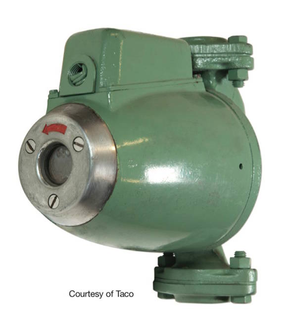
Figure 1 Photo courtesy Taco
A typical residential-scale wet-rotor zone circulator with a PSC (Permanent Split Capacitor) motor typically requires 60-80 watts of electrical power input, depending on specific model, where it operates on its pump curve, and what speed it’s set for.
Consider a reference circulator that operates on 70 watts power input. In a cold climate, and in system with a properly set outdoor reset control regulating supply water temperature that circulator may operate from 2500 to upwards of 4000 hours per year.
Let’s conservatively assume 2500 operating hours for a typical heating season. The electrical energy input to operate the 70-watt circulator would be:

If each kwhr of electricity costs $0.20, the seasonal operating cost of this circulator would be $35. Granted, most people can afford this, especially when the thermodynamic reality is that all 175 kwhr of electrical input eventually end off as heat, and in most systems that heat is created within the building’s thermal envelope. Thus, the 175 kwhr of electrical input to operate the circulator would convert to:
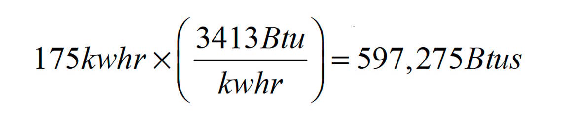
That’s enough heat to keep a house with a design heating load of 60,000 Btu/hr, comfortable for about 10 hours at design load conditions. Still, circulators are not intended to function as electrical space heating devices.
More Than One
So much for a single circulator. Many residential hydronic heating systems have at least three zone circulators, and perhaps other circulators providing flow in primary loops or through indirect water heaters.
Case in point: I once had the opportunity to inspect a house with 40 circulators. They were scattered throughout the 10,000 square foot custom home. Some in the mechanical room, some “hidden” in closets, and some accessible under stairs. Ironically, I was called to look at the project because even with 40 circulators, the hydronic heating system could not maintain comfortable conditions in the home.
Let’s put that system into perspective. 40 circulators operating at 70 watts each would require a power input of:

That converts to:
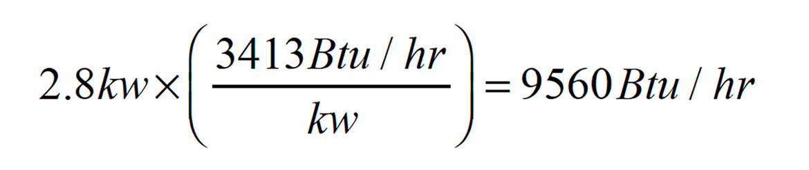
Perhaps on a mild spring or fall day the boilers in this house could remain off, while the electrical energy used to run the circulators satisfies the home’s heating load. Granted that I’m being sarcastic, but the numbers don’t lie.
Designing a system that requires 40 circulators in a house — even a big house — should be unacceptable, both from an installation and operating cost. Such a system literally destroys a significant benefit of a well-designed hydronic system — the ability to move heat from where it’s produced to where it’s needed in the building using roughly 10% of the electrical energy required by an equivalent forced air distribution system.
Looking ahead
DOE regulations based on the federal Energy Policy and Conservation Act have set May 22, 2028 as the end of the line for wet-rotor circulators in the US. Following that date, all legally sold circulators will be powered by electronically-commutated motors (ECMs). These circulators will have higher wire-to-water efficiency compared to those using PSC motors. They will also have self-contained and user-selectable control algorithms that allow the
circulator to change speed to maintain specific differential pressure conditions. The combination of high efficiency motors and automatic speed control will definitely reduce electrical energy input. Some manufacturers claim that upwards of 80% reductions are possible, albeit in specific applications involved valve-based zoning.
I don’t know how many wet rotor circulators with PSC motors are currently installed in hydronic heating systems across the US. I’m sure it’s well into the tens of millions. Eventually, those circulators will need replacement. That replacement might be the result of higher operating costs due to major increases in the price of electricity. It might also be driven by incentives, misapplication, building renovations, and failures due to poor water quality or other marginal operating conditions.
Consider the case of a residential hydronic system with four wet rotor zone circulators. Although it’s highly unlikely that all four circulators would fail at the same time, the possibility remains that they could all be “swapped out” with new ECM circulators based on significantly higher electricity prices, or the owners desire to lower operating cost, or incentives that largely subsidize the cost of the replacement circulators.
In most systems using on/off zone circulators, the operating mode of each circulator is typically a fixed speed curve. That’s because there are no on/off or modulating valves within each zone circuit. Without valves that open and close or modulate flow, the automatic speed control algorithms within most ECM circulators don’t apply. Thus, there’s no potential to reduce electrical energy use by reducing circulator speed under partial load conditions.
From Circulators to Valves
One option that reduces the electrical operating cost of systems with multiple (PSC motor) zone circulators is to replace all those circulators with zone valves and install a single variable-speed pressure-regulated circulator to provide flow to all zones.
Consider this hypothetical system: Four zone circulators with PSC motors, each pumping through identical zone circuits with equivalent lengths of 150 ft of 3/4” copper tubing. Each circulator operates with an electrical input of 70 watts. Assume these circulators operate for 2500 hours during an average heating season. The total electrical energy required for the circulators is:
(4 x 70 watts) x 2500 hours = 700,000 watt•hours or 700 kwhr.
A single ECM circulator operating at 44 watts peak along with four zone valves operating at 3 watts each, over the same 2500 hours of seasonal on-time would require:
(44 watts + 4 x 3 watts) x 2500 hours = 140,000 watt hours or 140 kwh.
That’s an 80% reduction in electrical energy.
Perhaps you think that a 44-watt ECM circulator pumping into four zones of 150 feet equivalent length each is too “wimpy” for the task at hand. That’s a reasonable reaction, especially considering that four circulators are being replaced by a single circulator.
To check this out, I used the latest version of the hydronics design studio software and found that a specific ECM circulator operating at 44 watts could produce a flow rate of 3.3 gpm in each of those zone circuits. If we assumed a 20 º F ∆T at design load, that’s enough flow to carry 33,000 Btu/hr to each zone, or 132,000 Btu/hr total.
When was the last time you did an accurate heating load estimate on typical 2500 square foot home and it exceeded 132,000 Btu/hr? Such a home would need about 52 Btu/hr/ft2 of heat input at design load. Many homes built or upgraded to current code standards will have design loads in the range of 10-20 Btu/hr/ft2. Those loads in this size home could easily be handled by the single ECM circulator / four zone valve system.
Flanged Foundation
Another likely reaction to replacing several zone circulators with an equal number of zone valves is how many piping modifications would be required. While a new ECM circulator will likely have to be cut into the existing piping, there is a way to simplify installation of the zone valves. In short, mount them between the existing circulator isolation flanges… Figure 2 shows the concept.
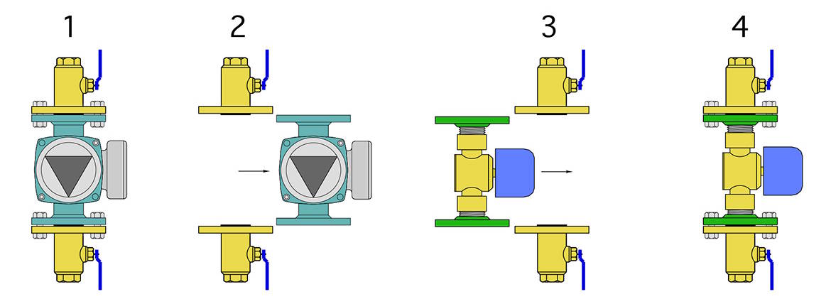
Figure 2 Diagram courtesy John Siegenthaler
Most zone circulators have a flange-to-flange dimension of 6.375 inches. If a “flanged zone valve” assembly can be created with (or very close to) the same overall length, it can just slide into place between the existing circulator isolation flanges.
I sent this concept to my friend Bob (Hot Rod) Rohr to get his thoughts. A few hours later, he sends me a photo of an assembly he built using some Caleffi fittings and Taco cast iron flanges (see figure 3).
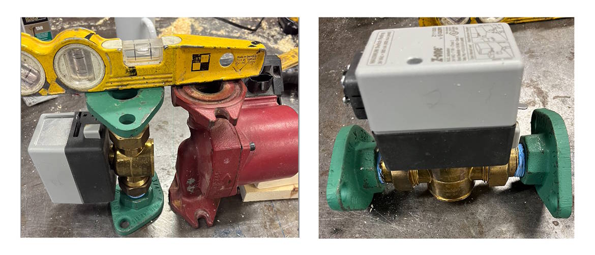
Figure 3 Photos courtesy of Bob Rohr
Although there are other possibilities, such as soldering two short lengths of copper tubing on either size of a brass zone valve body, and soldering the other ends of the tube stubs to bronze flanges, Hot Rod’s assembly doesn’t require any soldering. It uses a zone valve body that accepts multiple types of tailpieces. In this case it was 3/4” MPT brass tailpieces directly threaded into the cast iron flanges.
Repurposed
The most common voltage used for zone valve actuators is 24VAC, but several manufacturers also offer zone valves with 120 VAC actuators. If those were used in this application, the existing wiring installed for the zone circulators could be reconnected to the zone valves. The zone controller could also be used to operate the zone valves. With some zone controller it might be necessary to add a relay to turn on the new ECM circulator. That relay would be wired so that its coil is energized through the isolated (X X) contacts in the zone controller. The normally-open contact in the relay would then send 120 VAC to the ECM circulator when any zone was active.
Another option is to use zone valves with isolated end switches. Connect the end switch leads in parallel and wire them through a relay to send 120 VAC to the new ECM circulator whenever one or more of the zones are active.
An added benefit is that the original circulator isolation flanges remain in place. This allows any of the new zone valves to be isolated, repaired, or replaced with minimal water loss, and without additional isolation valves.
Figure 4 shows a before and after modification using the flanged zone valves.
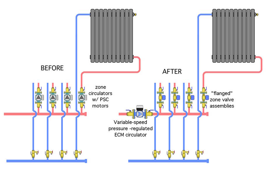
Figure 4 Diagram courtesy John Siegenthaler
Keeping Perspective
Well-designed hydronic systems have a decisive advantage over forced air systems when it comes to distribution efficiency. As a guideline, a well-designed hydronic system can create the same rate of heat delivery as a forced air system of equal thermal capacity while using only about 10% of the electrical energy required to operate the forced air system. Our industry doesn’t talk about this much, but it should! In the context of overall efficiency improvements, the energy required to “move” heat should be scrutinized along with the energy used to “create” that heat.
In most systems using on/off zone circulators, the operating mode of each circulator is typically a fixed speed curve. That’s because there are no on/off or modulating valves within each zone circuit. Without valves that open and close or modulate flow, the automatic speed control algorithms within most ECM circulators don’t apply.
Replacing older zone circulators with an equivalent number of new ECM zone circulators is one way to reduce electrical energy usage. In round numbers, such a changeout could reduce distribution electrical energy use by 50-60 percent. However, converting the system to zone valves and a single variable-speed pressure-regulated, based on the numbers discussed earlier, should up that savings potential to at least 75 percent.
If you have prospective customers who are very “tuned in” to maximizing the overall energy efficiency of their system, especially during a heat source upgrade, it’s worth having a discussion about distribution efficiency, and how a “hydraulic upgrade” can complement a “thermal” upgrade. Using flanged zone valve assemblies as part of the hydraulic upgrade can reduce repiping cost and speeds installation time. Keep it in mind when you evaluate existing systems for energy efficiency improvements.
Looking for a reprint of this article?
From high-res PDFs to custom plaques, order your copy today!