
The Glitch & The Fix: September 2026
The Glitch & The Fix: When a Heat Pump Retrofit Causes Reverse Boiler Flow
Can you determine what's happening with the air-to-water heat pump in this hydronic system?

The system shown in figure 1 is from a real installation. The intent of this project was to add an air-to-water heat pump to an existing hydronic system in which an oil-fired boiler supplied heat to several zones of low temperature floor heating.
The original installation is shown in figure 1. The modified system, which include the air-to-water heat pump and a buffer tank, is shown in figure 2. The modified system now operates on a 30% solution of propylene glycol antifreeze. A 2-stage boiler controller was installed and configured so that the heat pump would be the lead stage, and the boiler would fire if necessary to maintain the target supply water temperature to the zones.
When the system was put into operation the owner noticed that the boiler would often be warm even though the power switch to the boiler was off. Based on the flow rates shown in figure 2, can you determine what’s happening? Are there other design errors in this system? If so, can you identify them and come up with an alternative design that eliminates them?
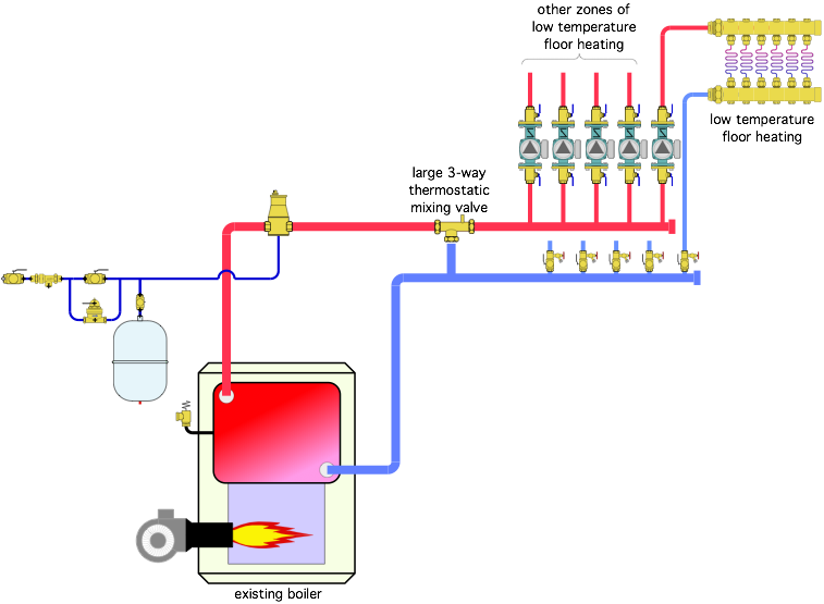
Image courtesy of John Siegenthaler.
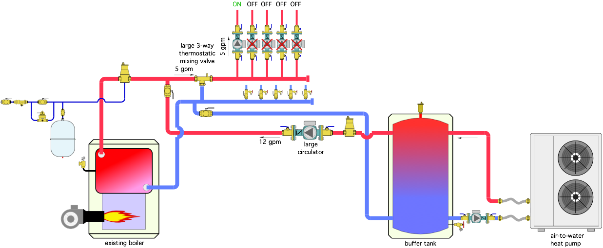
Image courtesy of John Siegenthaler
What’s Wrong
Before describing the shortcomings of the modified system, there’s one prominent error in the original system (figure 1): The cast-iron boiler is not protected against sustained flue gas condensation. Without this protection, the boiler and flue can be severely corroded. This was evident during a field visit. There was a prominent stain on the basement floor under an elbow in the vent connector leading upward to the chimney connection. The vent piping also showed signs of corrosion.
The Modified System
A large circulator was used to connect the buffer tank to the system. It could produce a flow rate of at least 12 gpm. Figure 3 shows what the other flows in the system will be based on the simple “accounting” that the flow entering a tee must equal the flow leaving that tee.
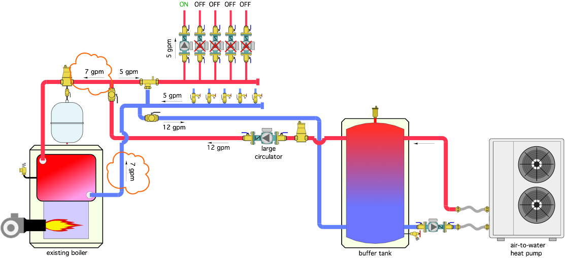
Image courtesy of John Siegenthaler.
When only one zone is operating the summation of flows into and out of the tees in the system shows that 7 gpm is flowing backward through the boiler. Hence the reason the boiler is warm even though it’s now firing. This allow convective air currents to develop inside the boiler, which carry heat up the flue and chimney. Sort of like having a small “cooling tower” attached to the heating system…
As additional zones turn on this situation might change to where flow through the boiler is in the correct direction. However, there should not be any flow through the boiler when it’s off. And the boiler is still not protected against sustained flue gas condensation.
The Makeover
Figure 4 shows one way the system could be modified to get proper flow, proper boiler protection, and keep the heat pump operating at high efficiency.
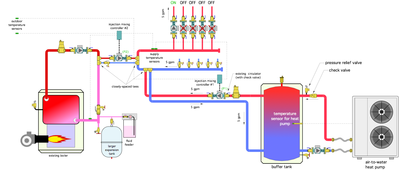
Image courtesy of John Siegenthaler
The reconfigured system leaves much of the “as found” piping in place. The buffer tank and boiler remain as stage 1 and stage 2 of heat input. The large circulator (P1) to the left of the buffer tank remains in the system, but is now operated by an injection mixing controller (injection mixing controller #1). That controller monitors the supply water temperature to the zone circuits and regulates the speed of the large circulator (P1) as necessary to keep the supply temperature at or very close to a target value based on outdoor reset control.
The heat pump monitors the temperature of the buffer tank and operates as needed to keep the buffer tank temperature just warm enough for the prevailing load conditions (based on outdoor reset control). This allows the heat pump to operate at the lowest possible water temperature and thus the highest efficiency (e.g., COP) based on current conditions.
Injection mixing controller #1 has an isolated boiler contact that closes if the heat pump can no longer keep the supply water temperature near its target value. This contact can be used to call for the boiler to operate, but only after a 15 minute interstage delay that gives the heat pump ample time to start, stabilize, and attempt to meet the target supply temperature.
The 3-way thermostatic valve has been removed and replaced by a variable speed injection circulator operated by injection controller #2. If the boiler is called to operate after the 15 minute time delay, injection controller #2 monitors the supply water temperature to the zones and controls the speed of injection circulator #2 as necessary to inject hot fluid from the boiler to the zone header system. The boiler contact within injection controller #2 operates the boiler as necessary. Injection controller #2 also monitors the boiler inlet temperature and slows the speed of circulator (#2) as needed to keep the boiler inlet temperature high enough to prevent sustained flue gas condensation. The original 2-stage boiler controller was removed (and saved for use on a future project).
The buffer tank and boiler both interface to the zone header system using pairs of closely spaced tees. These provide hydraulic separation of the two variable speed circulators and the boiler circulator. Note that the tees for the heat pump connect to the zone header system upstream of the tees for the boiler. This ensures the lowest possible operating temperature for the heat pump.
Other modifications include:
- Adding a pressure relief valve to the heat pump circuit to ensure that overpressure cannot occur if the heat pump were isolated from the remainder of the system and operated.
- Adding a check valve to prevent reverse thermosiphoning from the buffer tank through the heat pump.
- Removing the automatic water make-up assembly and replacing it will a fluid feeder (since the modified system with the heat pump is now operating with an antifreeze solution).
- Evaluating the size of the original expansion tank and upsizing it based on the added volume of the buffer tank and the higher expansion rate of antifreeze solutions compared to water.
Looking for a reprint of this article?
From high-res PDFs to custom plaques, order your copy today!