The Glitch & The Fix: January 2026
The Glitch & The Fix: Geo-normous problems
Pairing a non-modulating geothermal heat pump with a multi-zone, low-mass radiant system introduces several avoidable issues.

The Glitch
An installer is asked to provide a multi-zone, floor heating system supplied from a single stage non-modulating geothermal heat pump. The radiant floor panels will be low thermal mass. The system also needs to provide domestic water heating. The system he designs is shown in figure 1. Assume that the earth loop is sufficient for the capacity of the heat pump. Can you identify several problems that are likely to develop if this system is installed as shown?
FIGURE 1
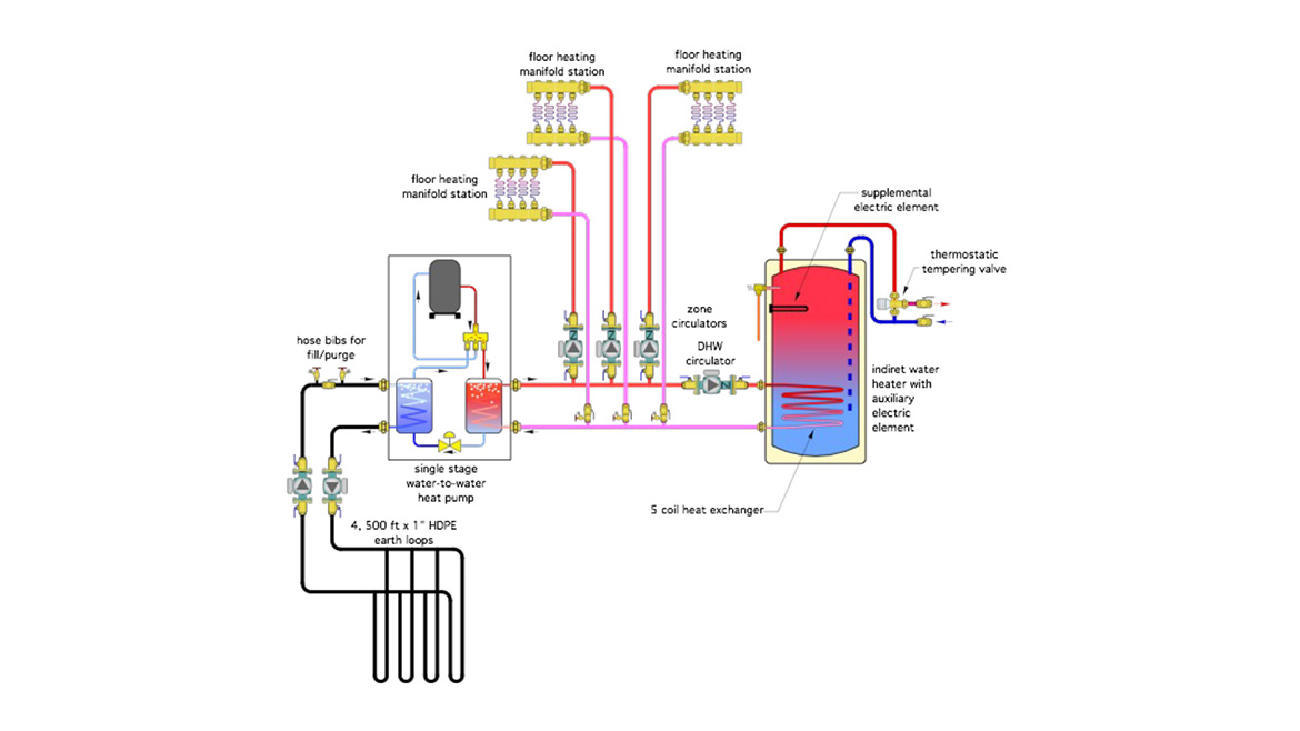
Drawing courtesy of John Siegenthaler
The fixes:
Any single stage non-modulating heat source coupled to a zoned distribution system is likely to experience short cycling, especially if the distribution system has low thermal mass. When only one or two zones are operating, they cannot dissipate heat into the building as fast as heat is generated by the heat pump. The water temperature between the heat pump and operating zones quickly increases and the heat pump turns off based on an internal temperature limit. It may or may not automatically restart depending on how its internal controls are configured. Even if it does restart automatically, the short cycling will be chronic.
The solution is to install a buffer tank between the heat pump and space heating loads as shown in figure 2. This allows the rate of heat generation by the heat pump to be very different from the rate of heat dissipation by the load. This tank, in combination with the generously sized headers, also provides good hydraulic separation between the zone circulators and the heat pump-to-buffer tank circulator.
FIGURE 2
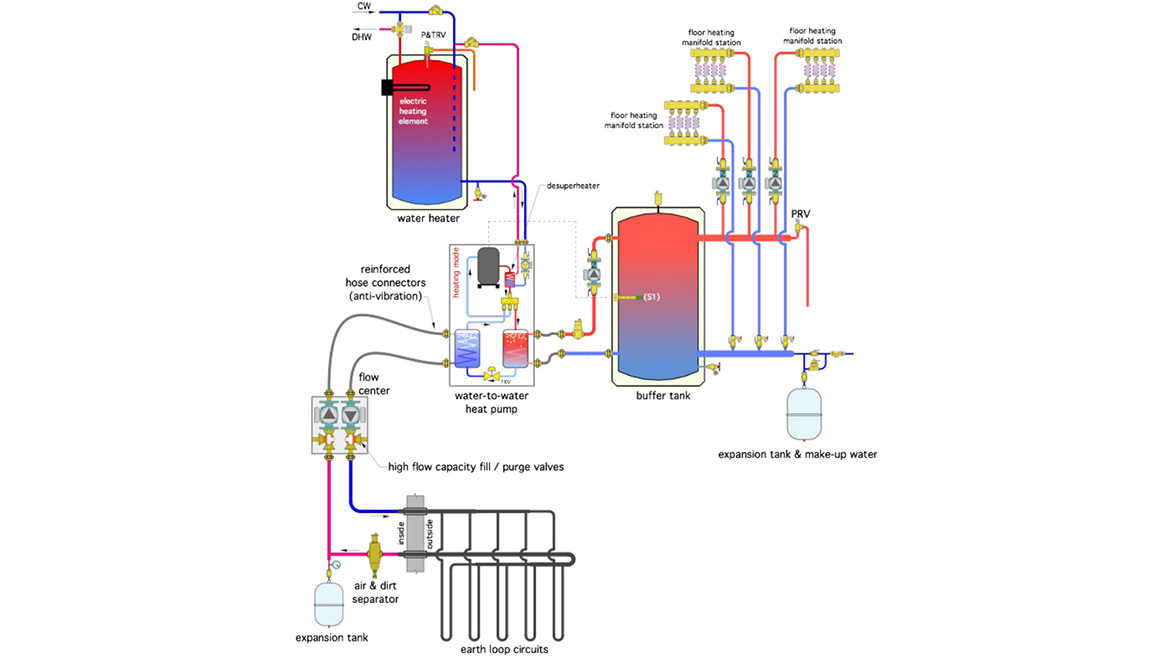
Drawing courtesy of John Siegenthaler
The coil heat exchangers in most North American indirect domestic water heaters simply don’t have enough surface area to dissipate the output of a 4- or 5-ton rated heat pump, while operating within the temperature limitation of that heat pump (typically 120 to 140 ºF depending on the refrigerant used). The coil won’t be able to dissipate heat into the tank as fast as heat is being generated by the heat pump, leading again to short cycling.
There are several alternatives for providing domestic hot water. The simplest is to select a heat pump equipped with a desuperheater heat exchanger. Heat from the hot refrigerant leaving the compressor is transferred to domestic water and moved to a standard electric water heater tank whenever the heat pump is operating. The upper electric heating element in an electric DHW tank provides any supplemental heating. This option is shown in figure 2.
Then there’s the earth loop. Even though there’s sufficient tubing in the ground, getting it filled and properly purged through a set of hose bibs is going to be very frustrating - if not impossible. It takes a substantial flow and differential pressure to simultaneously purge 4 parallel earth loops. The flow and head required often mandate use of a nominal 2 horsepower pump rather than small submersible transfer pump. Adequate purging flow requires much higher flow capacity purging valves. A common solution is to use a geothermal “flow center” specifically matched to the earth loop. Several types of flow centers are available with high-capacity fill / purge valves, and circulator options to match the flow and head loss of the earth loop.
I also recommend that the earth loop be equipped with a properly sized expansion tank, as well as an air/dirt separator as shown in figure 2. These allow for less pressure variation in the loop as it changes temperature, as well as cleaner / quieter flow.
Other issues with the system in figure 1.
- Some purging valves are upside down.
- There should be a purging valve on the return side of every load circuit.
- The inlet of the zone circulators is very close to the header. There should be at least 10 pipe diameters (10D) of straight pipe on the inlet to any circulator.
- There is no expansion tank or make up water hardware shown on the load side of the system.
- There is no air separator in the load side of the system.
- There’s no pressure relief valve in the load side of the system.
Looking for a reprint of this article?
From high-res PDFs to custom plaques, order your copy today!


.jpg")