Renewable Heating Design | John Siegenthaler
One way to increase the ∆T of a distribution system
Downstream details
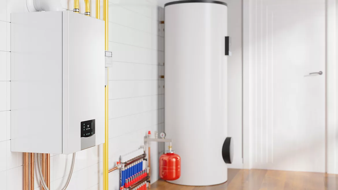
Modern hydronic systems benefit from wider temperature drops, energy scavenging, and careful integration with domestic hot water.
The coefficient of performance of a hydronic heat pump, (e.g., air-to-water or water-to-water), depends on the temperature at which its condenser operates. That temperature is largely determined by the hydronic heat emitters and distribution system the heat pump supplies. The lower the temperature of the water stream entering the heat pump the higher its COP, all other factors being equal.
Distribution systems capable of operating with relatively high temperature drop (e.g. ∆T) produce lower return water temperature to the heat pump.
Cast iron radiators and steel panel radiators can be operated at relatively high ∆T (by North American standards). For example, some European systems operate panel radiators with a 20ºC (36ºF) temperature drop under design load conditions.
Since the rate of heat transfer is based on the multiplication of flow times ∆T, the flow rate required for a given rate of heat transfer is inversely proportional to the ∆T. Changing the ∆T from 20 to 36 ºF at design conditions allows the flow to be reduced to (20/36) = 0.56, or 56 % of the flow required at at ∆T of 20 ºF. This reduction allows the potential for smaller distribution piping as well as lower input power to the circulator. Small tubing lowers installation cost. Lower circulator input power lowers operating cost. Both are beneficial in “tailoring” modern hydronics to low energy building trends.
One way to increase the temperature drop across the distribution system, while also leveraging energy at low water temperatures is shown in figure 1.
FIGURE 1
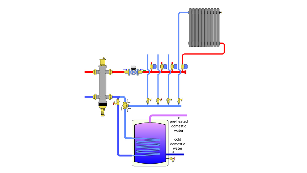
Image courtesy of John Siegenthaler
This assembly places a small indirect domestic water heater on the return side of the space heating distribution system. Its purpose is to absorb additional heat from the system fluid and use that heat to preheat domestic water.
Water returning from any of the active zone circuits passes through the coil of the indirect water heater, giving up heat to the cool domestic water. The extent of the preheating depends on the temperature and flow rate on the return side of the distribution system. It would also depend on the size of the internal coil heat exchanger in the tank, the volume of the tank, the frequency of hot water draws and the cold water temperature entering the tank.
The warmer the return flow from the distribution system, and the more frequent the draw of domestic hot water, the greater the rate of heat transfer at the coil.
This detail provides two very desirable effects:
- It lowers the fluid temperature returning to the heat pump - which helps boost its coefficient of performance (COP).
- It reduces the amount of heat needed to heat the domestic water to the required delivery temperature.
The 3-way ball valve can direct flow from the return side of the distribution system through the coil heat exchanger, or directly back to the hydraulic separator. If necessary, it can also isolate the inlet side of the coil if the preheat tank required service. The purging valve on the outlet side of the coil is used to fill and purge the circuit through the coil, or to isolate one side of the coil if necessary.
When wider is wiser
The allowable temperature drops across a heat emitter under design load varies depending on the type of emitter and the expected performance of that emitter.
Let’s start with a discussion on floor heating circuits. When installed in residences, floor heating is expected to produce “barefoot friendly” conditions. If a floor heating circuit operates at wide ∆T, there will be noticeable differences in floor surface temperature between areas near the beginning of the circuit compared to those near the end of the circuit. To minimize this effect, I suggest limiting floor circuit temperature drops to 10-12 ºF at design load.
The warmer the return flow from the distribution system, and the more frequent the draw of domestic hot water, the greater the rate of heat transfer at the coil.
When floor heating is used in an industrial building, such as a highway garage, “barefoot friendly” is not a concern since occupants are likely engaged in physical activities and walking around in work boots. In these applications, I suggest designing the circuit for ∆Ts in the range of 20-25 ºF under design load. Doing so allows for somewhat longer circuits and/or lower flow rates, both of which can reduce either installation or operating costs.
Steel panel radiators and cast-iron radiators can be sized for design load ∆Ts ranging from perhaps 15 ºF in low temperature systems, to as high a 35 ºF in higher temperature systems. The radiator’s heat output should be based on the average water temperature at design load. Using higher ∆Ts will lower the average water temperature and thus require more radiator surface area.
Fan-coils and air handlers can also be selected based on design load ∆Ts in the range of 20 to 30 ºF. As with radiators, base the heat output of the fan-coil or air handler on the average water temperature.
The boost
The temperature of the preheated domestic water leaving the indirect tank can vary widely. If the space heating zones operate frequently and at relatively high temperatures, the “preheated” domestic water might actually be hotter than desired for the building’s hot water delivery system. In systems where there’s infrequent operation of low temperature space heating zones, the preheating effect will be small. In this case, some type of supplemental domestic water heater is needed. There are lots of possibilities, including another indirect tank heated by the same heat pump or a boiler, an on-demand water heater, or a heat pump water heater. Figure 2 shows an example of the latter.
FIGURE 2
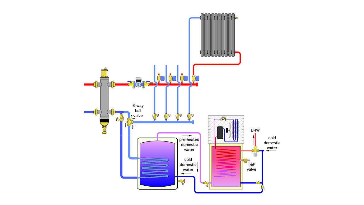
Image courtesy of John Siegenthaler
Under normal operation, the valving shown in figure 2 is set so that cold domestic water enters the lower portion of the preheat tank. The cold water inlet to the heat pump water heater is closed. However, if the preheat tank requires service or replacement the valving shown would allow it to be isolated. In such a case, the heat pump water heater would be the sole domestic water heater.
Another attractive benefit of the heat pump water heater is its ability to scavenge heat from an overheated mechanical room and put it to use. Case in point: I had an opportunity to visit a mechanical room this past fall. Although the outdoor temperature was around 35 ºF (in a location where sub-zero temperatures occur every winter), I estimated that the temperature in the mechanical room was somewhere between 90 and 100 ºF. The heat was coming from two boilers and several hundred feet of uninsulated copper and steel piping. Much of that heat would eventually leak out through uninsulated stone foundation walls built during the 1800s. A heat pump water heater would LOVE to operate in this environment, and would do so at a high COP.
More study needed
The benefit of the preheating tank is easy to comprehend qualitatively. What’s harder is a quantitative analysis to pin down the benefits versus cost. For example, in any given system what’s the optimal volume of the preheat tank and how large should its internal heat exchanger be? Bigger is likely better, but it’s also more expensive and it experiences higher standby losses.
The optimal preheat tank configuration would depend on the return water temperature from the space heating circuits, the entering cold water temperature, the timing and amount of domestic hot water draws, the cold water temperature, the heat loss through the jacket of the tank, the surrounding air temperature, the increase in COP of the main heat pump due to lower entering water temperature, and the efficiency of the heat source that does the final temperature lift of the domestic water.
The only practical way to find the net effect of all these variables would be through minute-by-minute computer simulation. I guess I should put that on my bucket list…
Looking for a reprint of this article?
From high-res PDFs to custom plaques, order your copy today!


