The Glitch and Fix: Lose the loop
The Glitch and Fix: February 2019

The Glitch:
The schematic in Figure 1 represents a drawing I recently reviewed for a proposed system that was to supply three zones of finned-tube based, two zones of low-temperature radiant panel heating, and an indirect domestic water heater. It called for a variable-speed circulator that responds to ∆P as the system’s “main circulator.”
Can you identify some probable operating problems if the system is installed as shown? Can you devise a better approach?

The Fix:
As shown in the Glitch drawing above (Figure 1), the ∆P circulator will experience very little change in flow resistance upon which to base its operating speed. The only change would be a slight drop in pressure as the zone valves supplying the baseboard zones and indirect water heat open and close. The key word here is slight. This is not a good way to apply a ∆P circulator.
Another possible problem is flow reversal at the closely spaced tees, depending on the flow rate in the boiler loop versus the radiant panel circuits.
There will also be a temperature drop around the boiler loop, which will depend on which loads are active. The good news is that the original design places the lower-temperature loads near the end of the loop. The bad news is that the temperature drop will not be consistent. Hopefully the thermostatic mixing valves can compensate. The key word here is hopefully.
Other issues include poorly placed hose bids that were likely installed with the intent of purging. They will help, but they are not going to work as good as properly placed purging valves.
One way to create a system which could serve the same loads is shown in Figure 2.
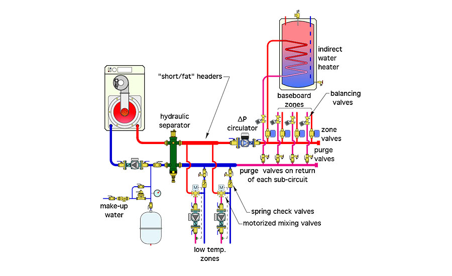
This design eliminates the extended boiler loop and sequentially placed closely spaced tees with a hydraulic separator and headers. All loop circuit draw from the load side header on the right side of the hydraulic separator. Those headers should be generously sized to limit flow velocity under full flow to about 2 feet per second. The headers should also be as short as possible. The goal is to keep the pressure drop of the headers, in combination with the hydraulic separator, as low as possible.
The hydraulic separator also eliminates the need for an air separator. It provides dirt and magnetic particle separation for the system. The latter is often recommended for systems with permanent magnet (ECM) circulators. That will provide good hydraulic separation of all the load side circulators.
The ∆P circulator would be set for constant ∆P, at a value that provides design flow rate through all the load circuits that it serves, and which could be on simultaneously. If the indirect water heater is operated as a priority load (generally a good idea), only the three baseboard circuits could be on simultaneously.
Each load circuit has a purging valve where it tees into the return header.
There are also spring-loaded check valves on the return side of each radiant panel subsystem. They protect against flow crossover between the headers, and through the motorized mixing valves, when the low temperature loads are off and the internal spool of the mixing valve is at an intermediate position.
Finally, I would recommend insulating all piping and components between the boiler and indirect water heater (at minimum). This piping will be carrying hot water during summer, and heat loss from it only contributes to the home’s cooling load in summer.
-John Siegenthaler
Please read here to view The Glitch and Fix: February 2019 in pdf form.
Looking for a reprint of this article?
From high-res PDFs to custom plaques, order your copy today!


.jpg")
