Hydronics Workshop | John Siegenthaler
How to integrate a heat pump with a boiler for dual temperature hydronic heating and cooling
Delivering expectations
Image courtesy of Olga Stabredova / iStock / Getty Images Plus
Consider a building with slab-on-grade floor heating supplied by a cast iron boiler. The owner wants to add more space to the building. The new space is expected to be heated and cooled. To provide the latter the owner wants to use a monobloc air-to-water heat pump to produce chilled water that will pass through a fan-coil unit equipped with a condensate drain. That fan-coil is also expected to provide heating for the new space. The heat pump will be the primary heat source for all areas of the building, the existing boiler will provide supplemental and back heating.
The heated floor is a bare concrete slab with good underside insulation and 12 inch tube spacing. It only requires 100 ºF supply water temperature to produce design load output.
The fan-coil unit needs 120 ºF water to provide design load heating output, and to avoid discharging low temperature air that creates drafts that compromise comfort.
How can all these requirements be met?
Piece of cake
Think back to systems where a single boiler needed to simultaneously supply two different water temperatures. The common solution was to set up the boiler controls to produce the higher temperature and then “mix down” for the lower temperature. If the boiler’s capacity was sufficient to meet the full load of the system this dual temperature requirement was straight forward. One example is shown in figure 1.
FIGURE 1

Image courtesy of John Siegenthaler
The heating-only fan-coil is a separate zone on the system. The low temperature floor heating is supplied by a variable speed injection mixing subassembly. The controller operating the injection circulator monitors boiler inlet temperature and reduces the injection flow rate when necessary to prevent sustained flue gas condensation within the boiler. For a gas-fired boiler the inlet water temperature is typically maintained above 130 ºF. The boiler outlet temperature would be 10-20 ºF higher than this inlet temperature depending on flow rate. Two loads, two different supply temperatures, simple, done.
When things get more complicated
Based on what the owner is expecting with the new heat pump it’s time to put that original system on the operating table. During that “surgery” it makes sense to keep as much of the original system as possible - assuming it has a role in the makeover. For example, the slab heating system, if sourced from what is soon-to-be the supplemental and backup boiler, still needs a mixing system. The boiler still needs to be protected against sustained flue gas condensation. So, keeping the piping assemblies that provide these functions, and doing so in a manner that’s least invasive to the existing piping is desirable.
The surgery also has to accommodate several new requirements:
- Adding a new fan-coil that handles heating and chilled water cooling;
- Accommodating new design load supply temperatures (120 ºF needed by the fan-coil, and the 100 ºF needed by the floor circuits);
- Bringing on the boiler when needed and making the heat it provides available to both the floor circuits and the fan-coil, without sending overly heated water to either load;
- The system in figure 2 shows one approach that meets these requirements.
FIGURE 2
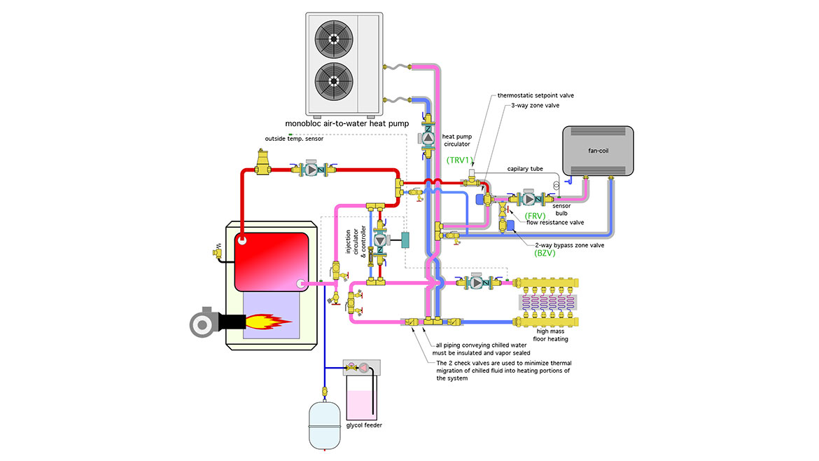
Image courtesy of John Siegenthaler
The best way to understand this system is to disassemble it into subassemblies.
Let’s start with the components that “preserve” the original boiler coupled to the heated slab using an injection mixing assembly. That subsystem is shown in figure 3 with non-related parts of the system stripped away.
FIGURE 3
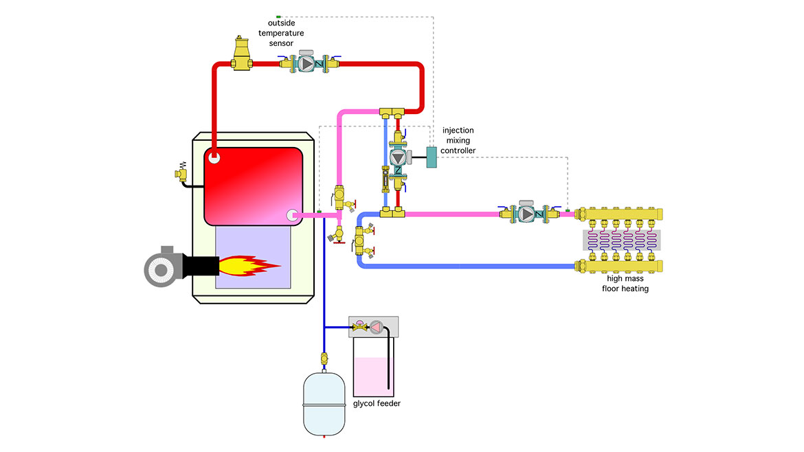
Image courtesy of John Siegenthaler
Most of the piping layout shown in figure 3 has been used in thousands of North American systems. The injection mixing controller uses outdoor reset to calculate the target supply water temperature to the floor circuits. It varies the speed of the injection circulator to regulate hot water flow from the boiler loop into the floor heating system. It also monitors the boiler inlet temperature, and when necessary, reduces the injection flow rate to prevent sustained flue gas condensation within the boiler.
Next, take a look at figure 4, it shows how the heat pump supplies both the floor heating subsystem and the fan-coil.
FIGURE 4
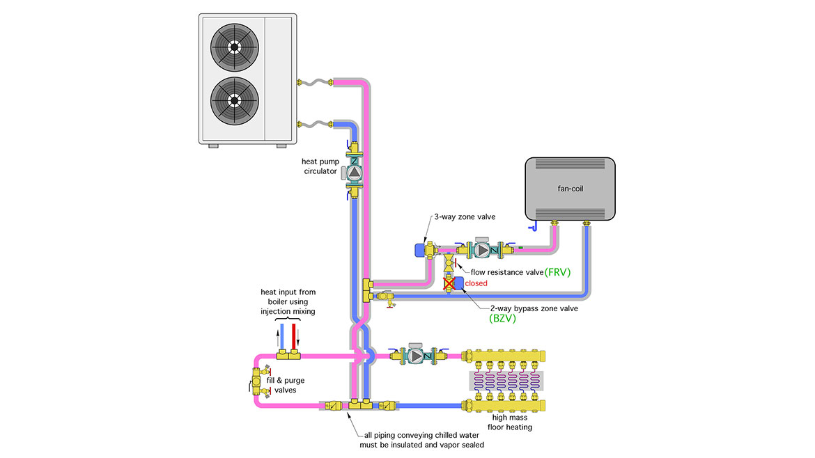
Image courtesy of John Siegenthaler
Assume the floor heating system is calling for heat, but the fan-coil is not. The heat pump circulator is on and drives flow into the closely spaced tees in the lower portion of the floor heating circuit. The heat carried by this flow goes to the floor circuits. No mixing is necessary. Keeping the temperature leaving the heat pump just high enough to meet the load of the floor heating system keeps the heat pump’s heating capacity and COP as high as possible.
The “X” crossover in the pink and blue piping is just an illustration that keeps the warm water injection point downstream of the return tee. As long as the actual installation keeps this injection point downstream of the return tee there no need to make the “X” in the piping.
Flow from the heat pump passes straight through the closely spaced tees that lead over to the inactive fan coil.
If the heat input from the heat pump drops below the outdoor reset setting of the injection mixing controller the boiler and injection mixing subassembly operate to increase heat input to the floor circuits. The heat pump continues to operate so that it’s heat output is combined with that from the boiler. Positioning the closely spaced tees supplied by the heat pump upstream of the tees supplied by the injection mixing assembly allows the heat pump to operate with the lowest water temperature (e.g., that of the water returning from the floor circuits). This keeps the heating capacity and COP of the heat pump as high as possible under the current operating conditions.
So far, so good
So what happens when the fan-coil turns on? If you follow the horizontal pink line starting at the upper tee in the supply from the heat pump, it passes through the 3-way zone valve, through the fan-coil circulator, through the fan coil, transfers heat to the coil, turns into the blue line, and goes back to the lower tee. The zone valve with the big red X across it is closed and plays no role in this mode.
But remember, the fan-coil needed 120 ºF supply temperature at design load, while the floor only requires 100 ºF? So how do you pull that off with the piping shown in figure 4.
This is where controls come into play. The heat pump, by itself, cannot simultaneously create two different supply water temperatures. However, it can create both the 120 ºF for the fan coil and 100 ºF for the floor circuits - one at a time. This is done by sharing the operating time between the two loads. This “toggling” action is easy to accomplish with many off-the-shelf zone relay centers that have a “priority zone”, and “priority override” capability. Here’s how it works.
First, setup the heat pump’s internal controller for 120 ºF leaving water temperature. Next configure the fan-coil as the priority load in the relay center. Whenever the fan-coil calls for heat, all other zones, which in this case is the floor heating subsystem, are temporarily turned off. This allows all heat output from the heat pump to go to the fan-coil. Assuming that the heat pump has the heating output to match or exceed the heat dissipation ability of the fan-coil at 120 ºF water temperature, it will operate to produce this temperature. If the heat pump has a variable speed compressor it may reduce compressor speed to stay as close to the 120 ºF outlet temperature as possible.
Any flow not drawn into the fan-coil will pass to the closely-spaced tees in the floor heating subsystem, but since floor heating is a non-priority load the circulator in that subsystem is turned off. This allows any extra flow not routed to the fan-coil to do a U-turn through the closely-spaced tees and go back to the heat pump.
Some zone relay centers have a priority override of 30 minutes, other allow up to an hour for the priority load to operate before overriding that load and turning on any other “non-priority” loads. Check the specifications of the zone relay center you are considering to confirm that it can toggle back and forth between priority and non-priority loads, and what time interval is required to do so.
If the fan-coil is off, or if the priority time out period is met, the zone relay center allows the floor heating system to resume operation - assuming that it’s still calling for heat. At that point the concept of thermal equilibrium dominates the situation. The water temperature leaving the heat pump will transition downward from the 120 ºF condition to a value where the rate of heat output from the heat pump matches the rate of heat dissipation from the floor. What that temperature is depends on current output capacity of the heat pump, as well as the current temperature of the floor slab. It might be a temperature where all is well (e.g., the floor is releasing all the heat from the heat pump, and keeping the building properly heated), or it might be at a low enough temperature that the floor output is not keeping pace with the building heat loss. Because the latter is definitely possible, the boiler and its associated injection mixing system need to turn on to supplement the heat pump. The “trigger” to activate the boiler and its mixing assembly should be based on outdoor reset control. This allows the heat pump every opportunity to be the sole heat source, especially on partial load days, but still brings on the boiler to ensure that comfort is maintained in the building.
Available when necessary
If the heat pump is down for service, the fan-coil can be supplied from the boiler. The piping used for this mode is shown in figure 5.
FIGURE 5

Image courtesy of John Siegenthaler
The 3-way zone valve is energized to open its top port and close its bottom port. The boiler and boiler circulator are turned on. Hot water from the boiler loop passes through a thermostatically- regulated injection valve (TRV1), through the 3-way zone valve, the circulator, and on to the fan-coil. The 2-way bypass zone valve (BZV) opens to allow some of the flow returning from the fan-coil to pass to the inlet of the circulator. The flow restrictor valve adds pressure drop as needed to induce flow through the thermostatic valve. It should be adjusted so that the thermostatic injection valve is at or close to its fully open position when the boiler loop temperature is near the low end of its cycling differential, and 120 ºF water is being supplied to the fan-coil. This condition might be present even when the flow restrictor valve is fully open. If so, just leave it along. If the water temperature reaching the fan coil is not making it to 120 ºF gradually begin closing the flow restrictor to force a higher injection flow rate.
Since a monobloc heat pump is installed, the system will mostly likely have to operate with an antifreeze solution. The original makeup water system is removed and replaced by a fluid feeder to maintain minimum pressure on the system and replaces minor fluid losses over time.
I would also recommend replacing the air separator with either a combined air / dirt / magnetic particle separator, or adding a dirt / magnetic particle separator to the system where it can collect any residual magnetite in the system before it passes into the new heat pump
Put it back together
Go back and look at figure 2. You’ll see that all the subsystems are there.
Perhaps you’re thinking this system is complicated. Well, based on what it’s expected to do, there is quite an assortment of hardware. But that hardware is all readily available from a many suppliers. It all works synergistically to optimize heat pump performance, protect the boiler, provide back if the heat pump is down for service, and most importantly ensure that comfort is not compromised. It comes together as another example of the versatility of modern hydronics.
Looking for a reprint of this article?
From high-res PDFs to custom plaques, order your copy today!


