
Hydronic Heating: Why 20°F Delta T Is Just a Number
The traditional 20°F Delta T is not a requirement for hydronic heating systems. Here’s how higher and lower temperature drops can improve system design, flow rates and efficiency.
President Abraham Lincoln began the Gettysburg address with the words “four score and seven years ago.…” Referring to time, the word score means 20 years. “Four score and seven” is certainly more poetic than just saying 87.
However, when it comes to hydronic systems, performance - not poetry - is what counts.
One enduring myth within the North American hydronics market is that all hydronic heating circuits should operate at a temperature drop of 20ºF. The origin of this number is unknown. Perhaps it came from the concept that if a system using water operates with a 20ºF temperature drop, the rate of heat delivery would be approximately 10,000 Btu/hr per gpm of flow rate. While this is a close approximation for the rate of heat delivery, it all hinges on the word “if.” More specifically, if the system operates with water, and if a 20ºF temperature drop occurs around the circuit, then each gpm of water flow rate would transport about 10,000 Btu/hr.
There is nothing special or advantageous about operating a hydronic heating circuit with a 20ºF temperature drop. In specific applications hydronic circuits can perform well using much lower and much higher ∆Ts.
For example, if a floor heating circuit operated at a very high flow rate its ∆T might only be 2 to 4 ºF. That would make the average water temperature in the circuit only 1 to 2 ºF lower than the supply water temperature. It would also make the floor area served by the circuit relatively uniform in surface temperature.
So, what’s wrong with operating a circuit under such a low ∆T? From the standpoint of heat transfer, and achieving relatively uniform floor surface temperatures, there’s nothing wrong. However, maintaining the high flow rate necessary for the low ∆T would require a larger circulator that would likely use significantly more electrical energy compared to that required to operate the circuit at a more typical ∆T of 10-15 ºF at design conditions.
Figure 1 shows the ∆Ts that would occur in a radiant floor heating circuit based on holding the inlet temperature constant at 110ºF, and varying the flow rate from 0.52 to 2.65 gpm.
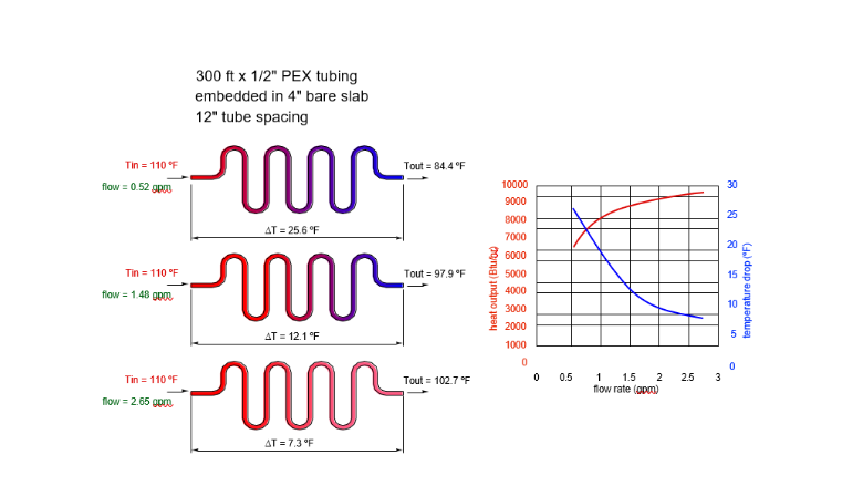
At the 0.52 gpm flow rate, the circuit’s ∆T is almost 26ºF. At the 2.65 gpm flow rate, the circuits flow rate would be 7.3ºF. The heat output of the circuit increases with increasing flow rate because the average water temperature in the circuit is increasing. However, the gains become smaller and smaller at higher flow rates.
Going Up
It’s also possible to operate hydronic circuits at temperature drops much higher than 20ºF. In Europe, some panel radiator systems are designed for a 20ºC (36 ºF) temperature drop at design load conditions. Using the higher ∆T allows the flow rates to each panel radiator to be reduced. The lower flow rate may also allow smaller tubing to be used to supply the radiator, as well as the possibility of a smaller circulator with lower power input requirements.
Figure 2 shows a thermograph of a panel radiator operating with an estimated 40 ºF ∆T between its supply and return water temperature. The ∆T was estimated based on the temperature scale and colors on the supply and return piping.
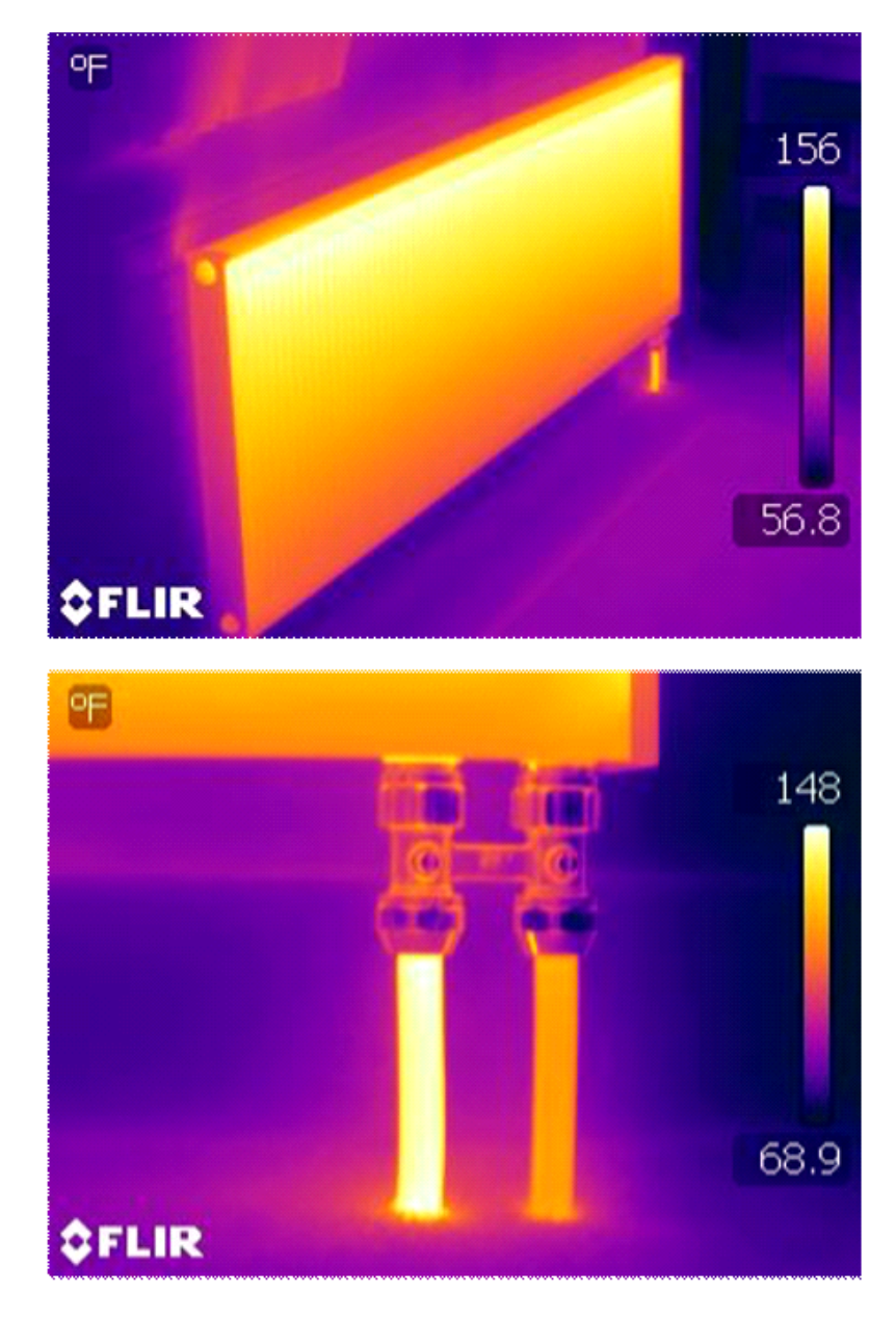
Notice the relatively even temperature gradient from the top to the bottom of the panel radiator. This indicates even flow distribution among the panels’ vertical flow channels.
Another example that leverages high ∆T is what I’ve come to call a “minitube” system. It’s based on the combination of a higher temperature heat source (such as a conventional boiler) and low temperature floor heating. The higher temperature water from the heat source is mixing with much cooler water returning from the floor heating circuits. However, this mixing occurs at the manifold station rather than in the mechanical room. This allows for a very high ∆T between the hot water traveling from the mechanical room to the manifold station, and the cooler water returning from the manifold station to the mechanical room. Figure 3 shows an example of a single zone miniature system.
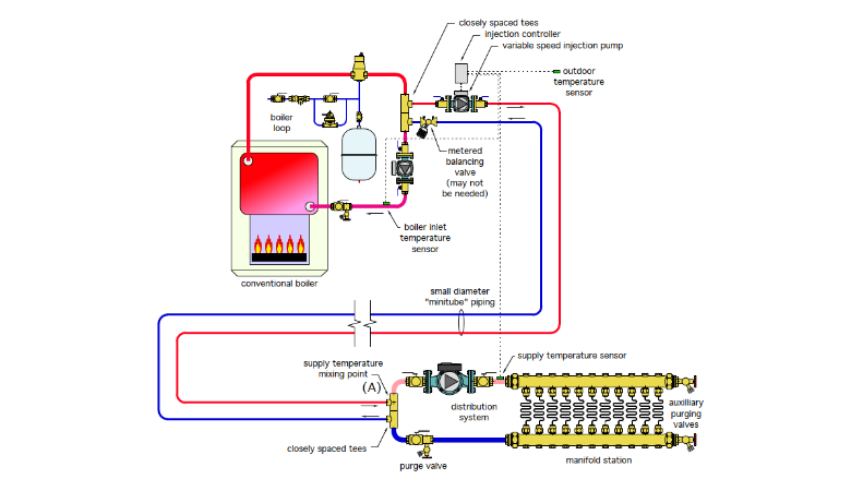
The term “minitube” refers to the small diameter piping running between the boiler loop and the manifold station. The small diameter is based on the relatively low flow rates needed when the ∆T is high. For example, assume that the manifold station requires a heat delivery rate of 200,000 Btu/hr. The outgoing water temperature from the boiler loop is 170 ºF, and the returning water temperature from the floor circuits, and back to the boiler loop is 90 ºF. The required flow rates is:
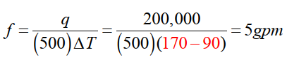
The flow rate can be handled by a 3/4-inch tube (copper or PEX-AL-PEX).
If the mixing had been done in the mechanical room, and the floor circuit temperature drop at design load was 15 ºF, the required water flow rate would be:
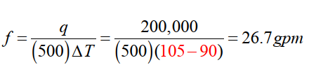
That flow rate would require 2-inch size tubing between the mechanical room and manifold station.
Consider a system where the manifold station is 100 feet (horizontal piping path) from the mechanical room, and run along the ceiling of the space, which adds another 50 feet of tubing requirement. The total tubing supply and return length between the mechanical room and manifold station would be 300 feet. Imagine the savings if 300 feet of 2-inch copper tubing plus associated fittings, hangers, etc. could be replaced by 300 feet of 3/4-inch PEX-AL-PEX. That’s the leverage of a high ∆T.
20 is just a number: There are certain numbers that seem to have a special significance in the natural world. Examples include Pi (3.141592654…), and “e” (2.7182818…), and the “golden ratio” (1.6180339887489…). The number 20 doesn’t make this list, nor should it. The temperature drop around a hydronic circuit can vary over a wide range. It will alway be the result of how much heat the circuit is dissipating, what fluid is circulating through the circuit, and what the flow rate of that fluid is. It’s also a number that will vary almost constantly since it’s very rare for any hydronic circuit to operate at true steady state conditions for more than perhaps a few minutes. Don’t assume that there’s something wrong with a circuit when you measure a ∆T higher or lower than 20 ºF. Likewise, if you happen to measure a 20 ºF temperature drop in a circuit, it’s not a guarantee that the circuit is delivering the amount of heat needed for the building area served by that circuit.
When circumstances permit, and comfort is not compromised, it makes sense to leverage a high ∆T. Doing so reduces the required flow rate, which may reduce pipe size and circulator power requirements. The ∆T of 80 ºF for the minitube system is a good example, 200,000 Btu/ hr transported on a flow rate of 5 gpm through 3/4” tubing. Perhaps if that ∆T was expanded by another 7 ºF (e.g.,from 80 to 87 ºF ∆T) you could log it down as “four score and seven.” Lincoln would be proud.
Looking for a reprint of this article?
From high-res PDFs to custom plaques, order your copy today!