Renewable Heating Design | John Siegenthaler
How to change the staging status of two heat sources
Who's on first?
Dual boiler systems have been around for decades. The basic concept is to turn on boiler #1 when the load requires heat, and turn on boiler #2 when the load exceeds the capacity of boiler #1, as evidenced by an inability to maintain the required supply water temperature. The parameter that’s monitored for making the decision to operate one or both boilers is typically a temperature, and the rate of change of that temperature. It might be the temperature in a buffer tank, or the water temperature supplied to the distribution system. The temperature control method could be based on a setpoint or outdoor reset control.
There are several multi-stage controllers on the market that can provide this functionality. Although they are typically called “boiler” staging controllers, they can often be applied to other heat sources, such as heat pumps or electric elements in a tank.
Some multi-stage boiler controllers can “auto-rotate” the operating order of the two heat sources. For example, after heat source #1 has operated for a specified number of hours as the lead heat source, the controller automatically changes it to the “lag” heat source. The objective is to accumulate approximately equal run hours on both heat sources, allowing both to be serviced and eventually replaced at the same time.
The “auto rotate” concept is well suited to systems where two or more identical heat sources are used. However, there may be situations where the decision to change the operating order of the heat sources needs to be based on other criteria, such as when one heat source has an operating cost advantage over the other.
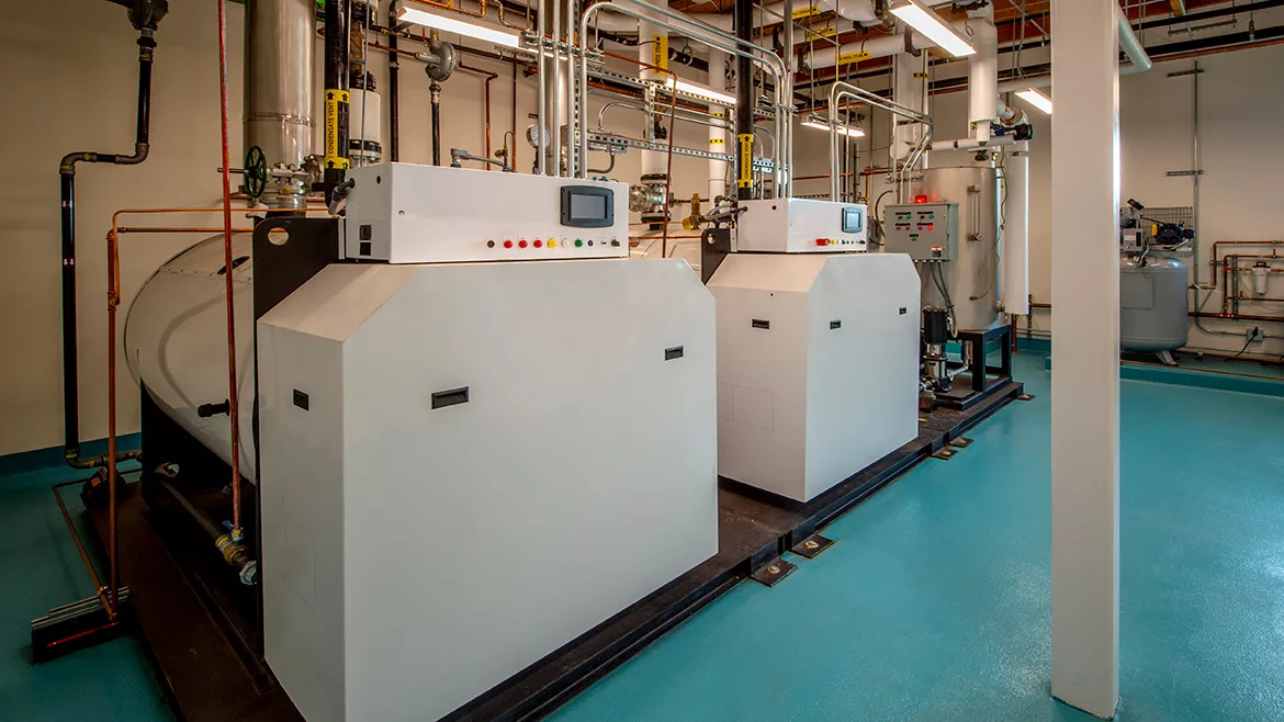
Consider the piping layout shown in figure 1.

Figure 1. Image courtesy John Siegenthaler, click to enlarge.
The two heat sources are in parallel, and connected to a common set of headers leading to a hydraulic separator. A 2-stage outdoor reset controller determines which heat source is turned on first, and, if necessary, it can turn on the other heat source to establish and maintain the required supply water temperature to the load.
Assume that there are times when the cost of off-peak electricity is such that heat produced by the electric boiler is less expensive than that produced by the propane-fired boiler. Under these conditions, the electric boiler should be the first stage to operate, with the propane-fired boiler only brought on as necessary to maintain the required supply water temperature to the load.
During “on-peak” hours heat produced by the propane-fired boiler is less expensive and thus it should be the lead heat source.
Making it happen
Let’s start with the simplest way of switching the operating order of the heat sources: a manual switch. Although it’s more likely that some form of automated switching would be used in most applications, understanding how the poles and throws involved with a manual switch operate makes it easy to apply the same logic to a relay.
If you’re not familiar with the terms “poles” and “throws” of a switch, please review my column “Relays & Switches” parts 1 and 2 in the PM archives.
Figure 2 shows how a 4-pole double throw (4PDT) switch would be wired between a 2-stage temperature controller and the two heat sources.

Figure 2. Image courtesy John Siegenthaler
This schematic assumes that the 2-stage controller uses two “dry” normally-open contacts for its outputs. It also assumes that each heat source requires a contact closure across the terminals labelled (T T) to enable its operation. This implies that the electric current flowing through the 4PDT switch and the contacts in the 2-stage temperature controller is sourced from each heat source.
The purple and blue conductors running between switch terminals are jumpers - short lengths of insulated wire.
Lots of screws
Most people are a bit intimidated when they have their first look at a 4PDT switch. It has 12 connection terminals. The switch shown in figure 2 happens to have screw terminals. Similar switches are available with quick connect “spade” terminals.
The switch in figure 2 is also an “industrial grade” switch capable of handling several amps of current through all its poles. Most low voltage control circuits only operate at a fraction of one amp, and thus the ampacity of an industrial switch is more than adequate. There are 4PDT switches with lower current ratings, but they are small and often intended for mounting on a printed circuit board. The challenge in field wiring these small switches is trying to make all 12 connections without inadvertently creating shorts between terminals.
I’ve found that the best way to wire a switch like the one in figure 2 is to create a short “pigtail” of insulated wired from each terminal. These pigtails can be about 10 inches long, and should be attached to each switch terminal using an insulated eyelet or an insulated female quick connector. It’s also a good idea to slide a piece of heat shrink tubing over each terminal once the pigtails are attached and use a heat gun to shrink them all at the same time. These details prevent problems such as having a tiny strand from one pigtail accidentally make contact with another terminal.
Once all the pigtails are in place, mount the switch on the side of a control cabinet and begin connecting the pigtails to the remainder of the control circuit using crimp connectors. You can always trim a few inches off any pigtail if necessary, but in general, it’s easier to leave sufficient wire length to allow the pigtails to be tucked back into the rear of the cabinet after all connections are made. This approach is a lot easier than trying to connect individual wires to each terminal after the switch has been mounted.
Be sure to identify each pigtail with a number that matches the number on the switch, and be sure to make a drawing showing where each numbered pigtail connects to the remainder of the control circuit.
Automated switching
Suppose you have a system with a propane-fired boiler and an electric boiler. You want the electric boiler to be the lead heat source whenever off-peak electric rates are in effect. These times will vary from one utility to another, but assume they apply from 11:00 PM to 7:00 AM on weekdays, as well as all day Saturday, Sunday, and on major holidays.
The owner obviously doesn't want to camp out in the mechanical room with a clock and manually move the 4PDT switch whenever the off-peak rate is in effect. You need an automated version of the 4PDT switch. Fortunately, that exists. It’s called a 4PDT relay. Figure 3 shows an example.

Figure 3. Image courtesy John Siegenthaler
This particular relay is an OMROM MY4 with 24VAC coil. The relay is shown alongside a matching socket with screw terminals. A schematic for wiring this relay to yield the same functionality as the manual switch is shown in figure 4.

Figure 4. Image courtesy John Siegenthaler
As shown in figure 4, with the relay coil off, heat source (a) will be operated when the stage 1 contacts in the 2-stage temperature controller close. Heat source (b) will be turned on, when needed, by the stage 2 contacts in the temperature controller. The staging action is based on the temperature ranges shown between the temperature control and relay. Most electronic 2-stage controllers can vary the temperature range of both stages over a wide range. These ranges can even overlap if needed.
The terminal numbers shown for the 4PDT relay are specific to the OMROM MY4 relay. Other relays may use other terminal numbers. Look inside the relay’s clear plastic case to identify which terminals are common, normally-open, and normally-closed (e.g. the common contact is the one that moves. When the relay coil is off the common contact touches the normally-closed contact. There is a slight gap between the common contact and the normally-open contact).
Then, look to see how those terminals fit into the relay socket and which screw terminals the go to. Use a multimeter to check for continuity if you’re not sure. Whenever the relay coil is off there should be continuity from the common contact to the normally-closed contact in all 4 poles.
For the wiring shown in figure 4, all that’s required to reverse the operating order of the heat sources is a 24 VAC signal to the coil of the 4PDT relay. This could come from an accurate digital timer with battery backup (so that its timing remains accurate during and following a power outage). It could also come from an isolated low-voltage dry contact in the utility meter. The latter method, if available, is preferred since it’s controlled by the utility meter and doesn’t require a timer. The timer method is fine, provided it’s accurate and precisely coordinated with the utility off-peak timing. Beyond these options would be any controller that can close a dry contact when it’s advantageous to switch the operating order of the heat source.
Hardened and documented
I’ve always been a fan of “hard-wired” control logic. The 4PDT switch and relay schematics presented are relatively simple examples of hard-wired logic. By combining switches and relays and wiring their contact in different combinations of series or parallel, it’s possible to create relatively complex operating sequences. The switches and relays I specify are industrial grade and as such very reliable. They’re also generic enough to be sourced from several suppliers, if necessary.
If you use the 4PDT switch or relay concepts described earlier, ALWAYS make a drawing showing and labeling every contact, every coil and every connection to the remainder of the control system. Make sure that drawing remains on site with other system documentation. Label every pigtail to correspond to the terminal numbers on the switch or relay and the terminals shown on your drawing. Don’t expect a technician - even a good one - to patiently reverse engineer your bundle of wires. Leave them a wiring roadmap!
Finally, there are alternates to the hard-wired logic shown in figures 2 and 4. Devices such as programmable logic controllers (PLCs) or micro-computers like Raspberry Pi or Arduino can operate contacts that could control the operating order of heat sources, and do so in ways that are only limited by programming instructions. Keep in mind that the switching hardware used in these solid-state controllers and micro-computers can be very limited in terms of amperage. If you need to control devices that operate at higher amperage, isolation relays will be required.
Looking for a reprint of this article?
From high-res PDFs to custom plaques, order your copy today!


