Hydronics Workshop | John Siegenthaler
Relays and switches — part two
Building the brains for custom hydronics systems.
Image courtesy of urfinguss / iStock / Getty Images Plus
Last month, we covered the basics of classifying switches and relays based on poles and throws. Once you learn these, it’s easy to apply switches and relays to create “hard-wired” control logic. The term “hard-wired” means that the logic is based on how the contacts of switches and relays (and the coils of relays) are wired together.
ANDs & ORs
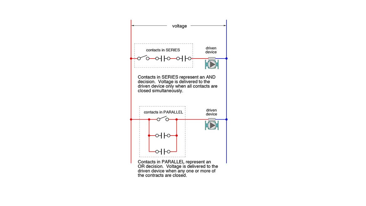
When any two or more contacts from a switch or a relay are wired in series they represent an “AND” logic state. Contact #1 AND contact #2 both have to be closed at the same time for a signal to pass through. An example from hydronics would be that the boiler disconnect switch, AND a contact in the boiler’s low water cutoff both have to be closed to allow power to reach the boiler’s burner.
When any two or more contacts from either a switch or relay are wired in parallel, they represent an “OR” logic state. An example would be the end switches from three zone valves, all wired in parallel. If switch #1 OR switch #2, OR switch #3 is closed, a signal to enable heat source operation is made.
Figure 1 summarizes these logic building blocks. In this case, the contacts are arranged in both AND and OR configurations. The result of the logic is whether a circulator is on or off.
Figure 1
Most controls systems are composed of multiple AND and OR logic states. One of the best ways to see this is to dissect a wiring schematic known as a ladder diagram, which is built up using switches and relays. But first, let’s look at the piping layout for which the control system is being designed (see Figure 2).
Figure 2
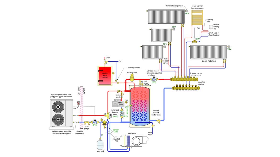
A monobloc air-to-water heat pump supplies heated water/antifreeze solution to a buffer tank. That tank is equipped with internal heat exchanger coils that preheat domestic water as it passes through them whenever hot water is drawn from a fixture.
An electric boiler serves as the supplemental and backup heat source. It’s piped in parallel with the heat pump. As you’ll see, it’s only allowed to operate if the heat pump cannot maintain the buffer tank within a prescribed temperature range.
Heat distribution is through a combination of panel radiators, a towel warmer, and a small area of floor heating. The latter two are combined in a master bathroom. Who doesn’t like a dry towel and a warm floor — especially when they occur together?
All zoning is handled by thermostatic valve operators on the radiators and a thermostatically- operated valve with remote adjustment dial controlling the flow to the towel warmer / floor heating circuit.
A small variable-speed pressure-regulated circulator (P3) runs continuously when the system is operating in heating mode. It’s set for constant differential pressure mode, and automatically adjusts speed based on the flow requirements of the heating distribution system.
The heat pump also provides chilled water/antifreeze to an air handler that distributes cool / dry air through a duct system.
From pipes to wires
Figure 3 shown the wiring schematic for the system shown in figure 2. Although some of the wiring is based on specific equipment, the concepts involved in the controls are common.
Figure 3
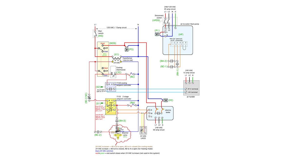
In addition to relay coils, contacts and switches, this ladder diagram contains some “embedded controllers” that open and close their internal relay contacts based on temperatures within the system.
Start at the top:
The power required to operate the control system is shown at the top. In this case, it’s a 120 VAC / 15 amp circuit. All that power has to flow through a master switch, designated as (MS). If that switch is open, the entire controls system is off.
Some of the driven devices such as the heat pump, air handler, and electric boiler, which are supplied on separate dedicated circuits, still have power available, but the logic used to operate them is unavailable when the main switch on the control system is open, and thus they cannot operate.
Moving downward on the wiring diagram you’ll find a transformer marked as (X1). It provides 24 VAC on its secondary winding, which powers several devices in the lower portion of the diagram.
The yellow-shaded rectangle in the upper left is a double pole / double throw (DPDT) switch, which also has a center “OFF” position. This switch is designated as (MOS), which is an abbreviation for mode switch. When the switch is off, the system will not operate in any mode. When the switch is turned to “heat” one of its poles passes 120 VAC to circulator (P3). Since there are no other contacts between this pole and the circulator, (P3) operates continuously whenever the mode switch (MOS) is set to heat.
Another conductor taps into the line voltage side of circulator (P3) to carry 120 VAC to a normally open relay contact in the electric boiler. That contact is completely under the control of the electric boiler. It closes whenever the boiler operates, and passes 120 VAC to circulator (P2), which creates flow through the electric boiler.
The second pole of the mode switch (MOS) does nothing when the switch is set to heat mode. Yes, it’s part of the switch, but there’s no need for it to pass a current when the system is operating in heating mode.
However, when the mode switch (MOS) is set to “cool” this second pole passes 24 VAC from the transformer to the cooling thermostat, designated as (TC). When this thermostat calls for cooling (e.g., when its internal contacts close), 24 VAC is passed to the coil of relay (RC). 24VAC is also passed to the “R” terminal on a temperature setpoint controller designed as (T150). This “wakes up” the T150 controller, which then monitors the temperature of chilled fluid entering the coil of an air handler. When that temperature drops to 60°F or less the contacts in the (T150) close enabling the blower in the air handler to operate. The “temperature check” provided by the T150 controller prevents a surge of warm air from the air handler if and when the heat pump has just finished heating the buffer tank, and thus contains heated fluid.
Going back up to the lower “cool” contact in the mode switch (MOS), you’ll also see that 24 VAC is passed to normally open relay contact RC-2. When the cooling thermostat (TC) calls for cooling, the coil of relay (RC) is energized, and contact (RC-2) closes. This passes 24 VAC to the brown lead of the motorized diverter valve. This, in turn, powers the diverter valve’s actuator motor to position the shaft to send chilled fluid from the heat pump to the air handler coil.
Are you starting to see how these switch and relay contacts work in concert to create the required logic?
Another red line from the secondary side of transformer (X1) energizes a 2-stage setpoint controller designated as (T152). The 24VAC power needed to operate this controller passes through a normally-closed relay contact designated as (RC-3 NC). You’ll see why this contact is necessary shortly. As a reminder, RC indicates that this contact is associated with relay coil (RC), -3 indicates pole number 3 on the relay, and NC designates normally closed.
When powered on, the controller (T152) continually monitors the temperature of the buffer tank. When that temperature drops to 95° F or less, the stage 1 contacts in the (T152) controller close. This energizes the coil of relay (RH). It also passes 24 VAC through normally closed relay contact (RH-3) to apply 24 VAC to the black lead of the diverter valve. This puts the diverter valve in the position needed to send heated fluid from the heat pump to the buffer tank. Relay contact (RH-1) and (RH-2) also close to turn the heat pump on, and put it in heating mode.
All this is necessary to send heat from the heat pump to the buffer tank, and this sequence happens regardless of the mode switch (MOS) being set for heat, cool, or off. The reason is to enable the buffer tank, which provides most of the heat for domestic hot water, to be maintained at an elevated temperature regardless of the space heating or cooling needs of the building.
However, when the cooling thermostat calls for cooling, energizing relay coil (RC), contact (RC-2) powers the diverter valve to the cooling position, (e.g., brown lead of valve energized), and contact (RC-3 NC) interrupts 24 VAC from the heating controller (T152), and thus interrupts 24VAC from the black lead of the diverter valve. This logic treats a call for cooling as having priority over keeping the buffer tank at an elevated temperature. Under this temporary condition, the auxiliary DHW heater would be responsible for keeping DHW available.
If the temperature of the buffer tank drops to 90° F or less, and the cooling thermostat is not calling for cooling, the stage 2 contacts in the (T152) controller close. This passes 24AC from the transformer in the electric boiler to the low water cutoff (LWCO) protecting the boiler. If fluid is detected at the (LWCO), the 24 VAC signal passes through enabling the electric boiler to operate. A relay within the electric boiler closes to pass 120 VAC to circulator (P2) to create flow through the boiler. The electric boiler has an internal high-limit controller that will turn off its heating elements if the water temperature reaches 120° F or higher. However, under normal operation, it will be turned off by the stage 2 contact in the (T152) controller when the temperature in the buffer tank climbs to 104° F
Narrate what you create
Perhaps I’ve convinced you, based on the above descriptions, that the old adage: “A picture is worth a thousand words” certainly applies to control system documentation. Still, a picture alone, without a detailed description of operation makes it harder for a technician to quickly understand how the system is supposed to operate. The ideal scenario when creating custom control systems is to provide a piping schematic, wiring schematic, and a full description of operation. Be sure to coordinate the labeling of components such as circulators, motorized valves, sensors, etc. between all drawings and descriptions.
I hope that you’ll appreciate how relays and switches are powerful components in creating specific and robust control systems for all types of hydronic system applications. Learn the basics and enjoy the “power” these devices afford for creative design.
Looking for a reprint of this article?
From high-res PDFs to custom plaques, order your copy today!


