Column | John Siegenthaler
John Siegenthaler: Relays and switches — part one
The basics.

Image courtesy of Michael Edwards / iStock / Getty Images Plus
Many current-generation residential HVAC product providers sell their wares as a system. A typical air-to-air heat pump system is a good example. If it’s a ducted system, the air handler, refrigerant line set, outdoor condenser unit and even the thermostat are typically sold as a matched set of components. It’s a similar story for ductless heat pumps. A given condenser unit is rated to handle a specific number of specific indoor wall units. The DX line sets are all prescribed along with allowable lengths based on the refrigerant pre-charge in the condenser units. The controls are typically hand-held remotes.
This approach is nice in that it simplifies design and product selection. It also ensures compatibility between all the major components involved.
Unfortunately, the North American hydronics industry is not as far along in pre-engineering and pre-configuring its systems. Although some suppliers are making things easier, such as offering boilers that can manage multiple zones without additional controls, or heat pump systems that simplify piping installations, there are still many circumstances where customization is required for piping and controls.
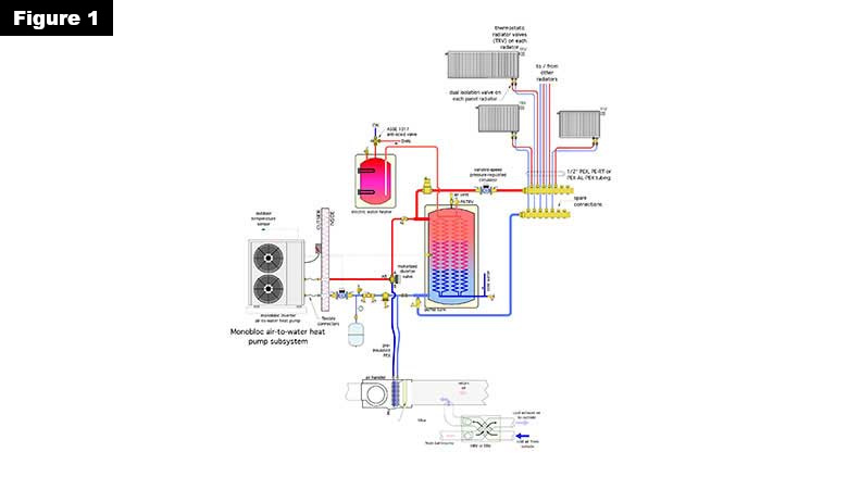
Here’s an example: A hydronic system will be designed to provide heating, cooling and domestic hot water using an air-to-water heat pump. The designer wants the heating portion of the system to be panel radiators, each with its own thermostatic radiator valve. A small, low-power circulator will operate continuously during the heating season to supply heated water to any radiator that “asks for it.”
With this approach, there is no need for a heating thermostat (or multiple zone thermostats) to regulate space heating. Say “nice, but no thanks” to contemporary thermostat offerings such as NEST, Z-WAVE, Ecobee and a host of other Wi-Fi-enabled devices.
Building cooling will be a single-zone chilled water air handler supplied by the air-to-water heat pump. Air will be distributed throughout the building by a duct system. The portion of the system needs a “cooling-only” thermostat.
Domestic water heating will be done using the system’s buffer tank to preheat cold water and top off the temperature with an electric tank-type water heater.
That’s quite a mix of approaches, but, thanks to the versatility of modern hydronics, it’s a very doable system from a piping and controls standpoint.
Figure 1 shows one potential piping diagram for this system.
Building the brains
As HVAC controls have evolved over the last several decades, much of the “logic” needed to make operating decisions have moved from electro-mechanical devices such as switches and relays to microprocessor-based controllers, where a prescribed set of instructions is “burned” into the non-volatile memory (EPROM or EEPROM) of the controller.
Still, when comes time to turn on a line voltage device such as a circulator, fan, heating element, or compressor, the logic portion of the controller has to signal a relay or contactor to “put the juice” to the load. Hundreds of relays and contractors are available that can handle the higher amperage draw of these devices.
Relays and Switches have also been used in industrial control systems for decades. When applied within their voltage and current ratings these robust devices typically last through millions of operating cycles. They are also more tolerant of electrical abnormalities such as brownouts, voltage spikes, arcing or the presence of electromagnetic fields, all of which can “confuse” or wipe out microprocessor-based controllers that operate on low voltage and microamps of current.
Relays and switches can be extremely useful as building blocks for customized system controls.
The basics
Relays and switches are classified based on the number of “poles” and “throws” they have. A pole is simply an isolated current path through the switch or relay. A throw is the number of states the device can have where current can pass through it.
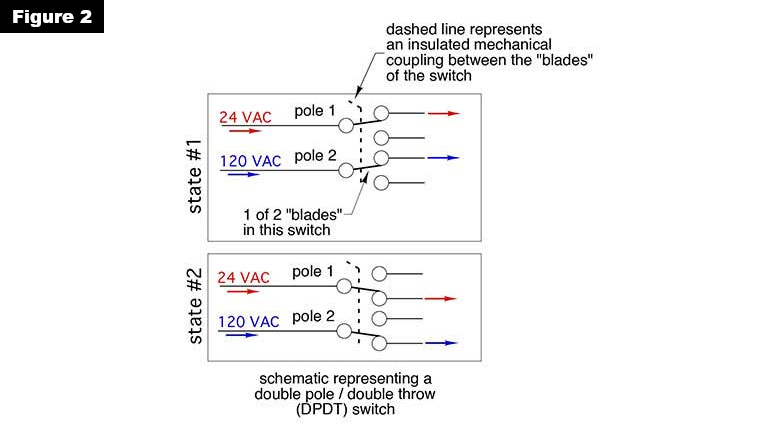
Let’s consider a double pole/double throw switch (abbreviated as DPDT). It could have two independent current paths (e.g., poles). One pole might pass a current through a line voltage circuit, the other might pass a current through a 24 VAC (volts AC) circuit. This combination can be very helpful in control system design.
The “double throw” designation means that the switch can pass a current in two “states.” One state is when the lever of the switch is in one position. The other state is when the lever is moved to another position — other than off — where a current can pass through.
Figure 2 illustrates the concept of a double pole/double throw switch.
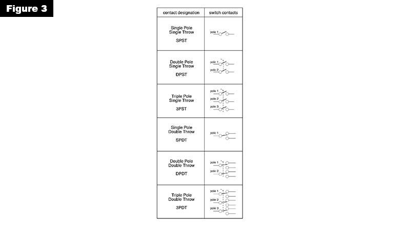
If you understand the basics of poles and throws, it’s easy to imagine switches with more or less of them. Figure 3 shows the schematic symbols for switches with up to three poles, and both single and double throw configurations.
Relays are simply electrically-operated switches. When a current flows through the coil of a relay it creates a magnetic force that causes the contacts to move. When the current through the coil stops, an internal spring returns the contacts to their “normal” position. Figure 4 shows the components in a typical relay.
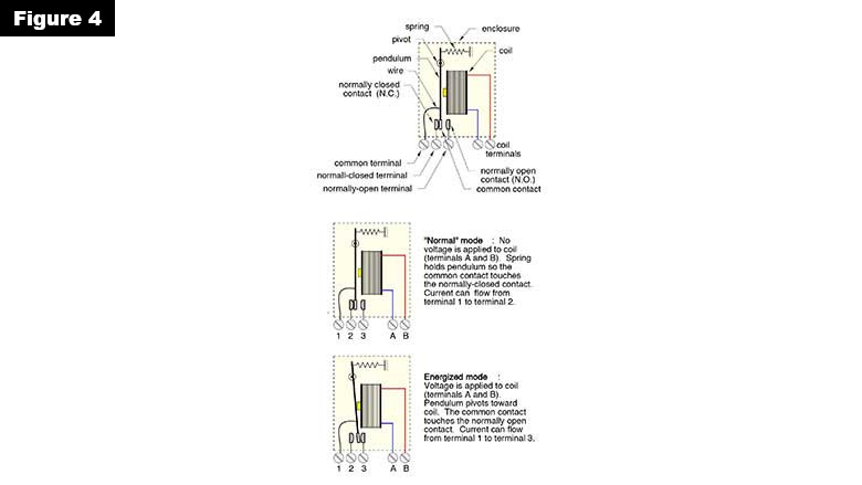
If the contacts were open before the current is applied to the coil, they are designated as “normally open.” If the contacts were closed before the current is applied to the coil, they are designated as “normally closed.” The one contact that participates in both normally open and normally closed states (e.g., the contact that moves within the relay) is called the “common” terminal.
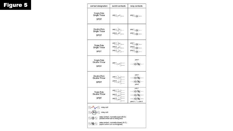
Figure 5 is an extension of Figure 2. It shows the previously discussed poles and throws of switches, and adds the poles and throws of relays. It also shows the schematic symbols used to represent the coil of a relay. Compare the similarities between switches and relays that have the same number of poles and throws.
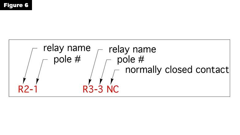
All relays have a single coil but many have multiple contacts, both normally open and normally closed. Furthermore, there are often multiple relays used in a control system. To keep designations consistent and unique, relays are labelled as shown in Figure 6.
The name of a relay isn’t limited to just R1, R2, etc. It could be Rh, Rc, Rdhw, Rcirc, or other ames starting with “R.” Figure 7 shows how these labels apply to the coil and contacts of a triple pole/double throw (3PDT) relay.
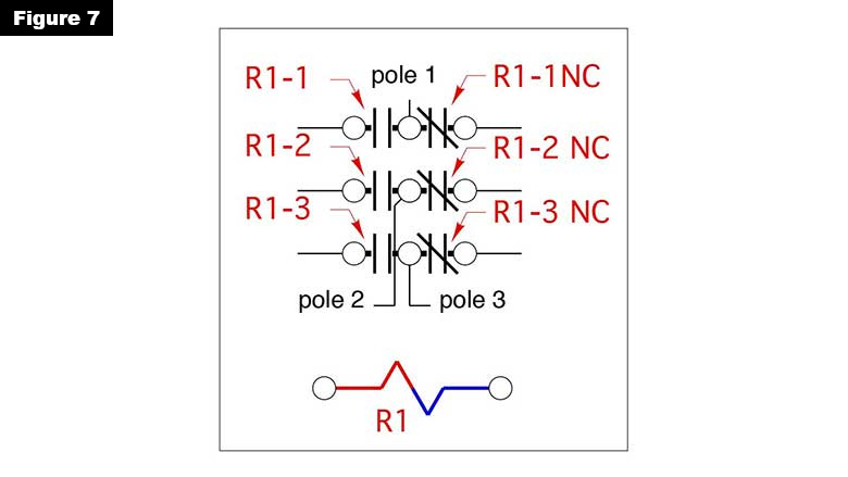
Although Figure 7 shows all the contacts and the coil in close proximity, and indeed they are all in close proximity within the physical device, they are often spread out within a typical control drawing. That’s why the labeling system is so important. Regardless of where the coil or a particular contact appears in a schematic, the label always shows what relay it belongs to.
Two other important identifiers are used with relays:
- Coil operating voltage (120 VAC, 24 VAC, 5 VDC, 12 VDC as examples); and
- Contact current rating (5 amps, 20 amps, as examples).
The coil operating voltage is a nominal value. A relay with a 24 VAC-rated coil will likely operate if the voltage applied to the coil is 22 volts or 27 volts.
The current rating of the contacts is the maximum number of amps the contacts are rated to carry. Some relays further refine the current rating based on the load being “resistive” versus “inductive.” A resistive load would be a heating element or an incandescent bulb. Motors or any type of electromagnet would be examples of inductive load. The inductive current rating of a relay is typically less than (about half) of its resistive current rating.
More to come
So much for all the nomenclature. In next month’s column, we’ll put the contacts and coils of multiple relays together to create operational logic. You’ll soon see that an understanding of relays and switches is essential in creating control systems that behave exactly the way you intend them to.
Looking for a reprint of this article?
From high-res PDFs to custom plaques, order your copy today!


