John Siegenthaler: Drawn to professionalism: Part 3
In my May Hydronics Workshop column, “Drawn to professionalism: Part 1,” we discussed the importance of good documentation as part of a complete system design and installation. In June’s column, “Drawn to professionalism: Part 2,” we looked at piping and electrical schematics, a description of operation, and listing of initial controller settings, all combined as a documentation package.
This month, we’re concluding the series with an overview of the tools available for creating this documentation.
‘A picture is worth 1,000 words’
This statement supposedly has origins in an ancient Japanese philosopher. It certainly holds true when it comes to communicating the details of a hydronic heating or cooling system, where the “pictures” take the form of schematics.
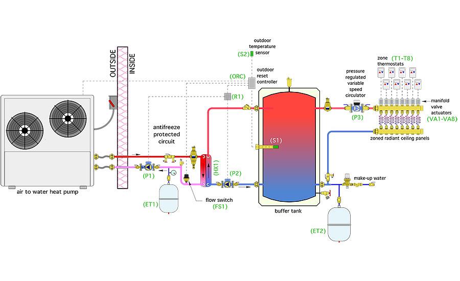
A piping schematic shows the relationship between all major components in the hydronic system. It should include symbols for all heating or cooling sources, valves, circulators, heat exchangers, tanks, separators, instrumentation, and specialty components. It doesn’t have to include symbols for common fittings like elbows or tees.
Piping schematics are not scale drawings. Still, they should show a reasonable depiction of the relative size of components (for example, a ¾-inch check valve should not be as large as a 119-gallon thermal storage tank).
Piping schematics should be arranged with the heating or cooling sources on the left side of the drawing and the heat emitters or cooling terminal units on the right. This represents the path of thermal energy flow through the system in the same order as one would read a line of text.
Figure 1 shows an example of a relatively simple piping schematic.
Current pathways
Electrical schematics also show the relationship between all major electrical components in the system. They should include symbols for all controllers, switches, relays, transformers, fuse blocks, motors, heating elements, and electrically operated valves. They do not have to include symbols for commodities such as wire nuts or spade terminals.
Electrical schematics can be created as point-to-point drawings that show the exact path of every conductor in the system from a specific terminal on one component to another specific terminal on another component — or, in some cases, to the same component. They can also be created as a ladder diagram, as shown here in Figure 2.
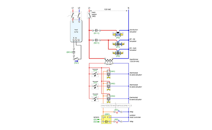
I recommend ladder diagrams because they are relatively easy to create and modify. They also create order and help keep thinking focused as circuits are designed.
Ladder diagrams start with a callout for the power source at the top of the ladder. For 120-VAC systems, line voltage is represented by a vertical line that forms the left side of the ladder. Neutral is represented by a vertical line forming the right side of the ladder. Any “rung” across these two vertical lines needs to contain a device that operates on 120 VAC.
Common examples are circulators, fan or blower motors, 120-VAC motorized valves, or “embedded controllers” such as a multi-zone relay center. The lowest rung of the line voltage ladder typically contains a step-down transformer, which serves as the power source for the low voltage portion of the ladder and is drawn below the transformer. Many hydronic systems have 24-VAC electrical components that would be shown across this lower portion of the ladder.
One advantage of ladder diagrams over point-to-point schematics is that the ladder can be lengthened as necessary to accommodate all the line or low-voltage components. This is especially easy when CAD (computer-aided drawing) systems are used to make the drawing.
Starting with a sketch
I spent 13 years of my engineering career using a drafting table, pencil and paper for creating all types of system documentation. With experience, I could plan out use of the paper space to accommodate the necessary details of the drawing.
However, in the process of gaining experience, I often found I had too many details and not enough paper space, or vice versa. It’s also very likely the design would evolve after some of the schematic was committed to paper. These situations made changes to the drawings very time-consuming and messy.
One way to reduce the need for changes is to make a sketch before moving to final drawing tools (drafting board or CAD system). A sketch helps solidify the details, and it also helps in proportioning the space needed for the drawing. It doesn’t have to be neat, but it should show sufficient detail and approximate component placement to allow you, or perhaps someone else, to make the final drawing.
If you will be moving on to the final drawing right after doing the sketch, it’s OK to simplify the level of detail. However, if it’s likely to be a while before the sketch gets used to make the final drawing, or if someone else will use the sketch to make that drawing, it’s wise to spend more time to add more details, especially when you’ve come up with some novel detail that you don’t want to forget before getting to that final drawing.
It wasn’t long ago when tools such as drafting tables, symbol templates, and vellum (semi-transparent high quality drawing paper) were essential tools for drawing piping or electrical schematics. For that matter, it was only about 40 years ago when typewriters were the standard tool for creating text documents.
One could argue it’s still possible to use these tools today for creating system documentation. The person supporting that argument might also be comfortable installing a complete and complex hydronic system using threaded iron pipe, or building a house using a hand saw. Trust me, if you intend to do schematic drawings now or in the future, you need a CAD system.
The evolution of CAD
Thirty years ago, CAD software cost several thousands of dollars, and several thousand more was needed for high-end computers that could run numerically intensive CAD software at a reasonable pace.
Beyond the hardware and software costs was a huge commitment in time necessary to gain proficiency with early generation CAD systems. Large engineering and architectural firms could make these investment, but CAD was far too expensive and complex for small firms or installing contractors.
Fortunately, that situation has changed dramatically. Today, CAD software capable of making professional looking schematic ranges from literally free to perhaps $400.
Free CAD is as close as a Google search. The usual rationale behind free CAD software is to provide a limited-function version that is good enough to justify some investment in learning time, followed by the enticement of more features in the for-sale “pro” version. The “hook” is the investment in learning time.
Once a user gets comfortable using a specific CAD system, it’s hard to break the habit and recommit to learning a different CAD software. The price to upgrade to a pro version of the software is seldom the obstacle — it’s relinquishing the established productivity that keeps established CAD users from straying away from the software they’ve learned. CAD software developers know this and are willing to bet that enough of those using the free version of their software will eventually open their wallets to sustain their investment in the learning curve and created drawings.
There’s also free open-source CAD software. It’s developed by a group of voluntary collaborators who add bits and pieces of functionality over time. It generally works, and some individuals use it, but it’s not subject to competitive market forces that mandate continued improvement as the only alternative to obsolescence or being outdone by competitive software offerings.
Open-source CAD software can also be a bit more “buggy” because no one individual or company is ultimately responsible for how it works. There’s also the possibility that open source software will eventually go unsupported, which quickly leads to obsolescence. These issues concern most engineering and architectural firms who need assurance that their capital and training investments in CAD software are sound and sustainable.
Just the basics
While using a full-blown CAD system, free or otherwise, to make piping and electrical schematics is certainly possible, it is hardly necessary. It’s like buying a 1,000-piece collection of shop tools for the purpose of occasionally using one or two screwdrivers and an adjustable wrench.
My belief is that most hydronic professionals need a tool for making piping and electrical schematics that’s designed specifically for that task, is simple and intuitive to learn, and allows them to make an accurate schematic that can be easily captured as a PDF file or sent to an inexpensive inkjet printer. Those schematics would be used for cost estimating and installation. They also provide value to system owners and serve as sales tools for prospective customers.
To read Siegenthaler’s article “Drawn to professionalism: Part 3” in pdf form, please see here.
Looking for a reprint of this article?
From high-res PDFs to custom plaques, order your copy today!


