Renewable Heating Design | John Siegenthaler
Elegance extended: How to use the homerun system of connecting heat emitters
The 'homerun' method of connecting heat emitters is simple, elegant and most importantly, effective.
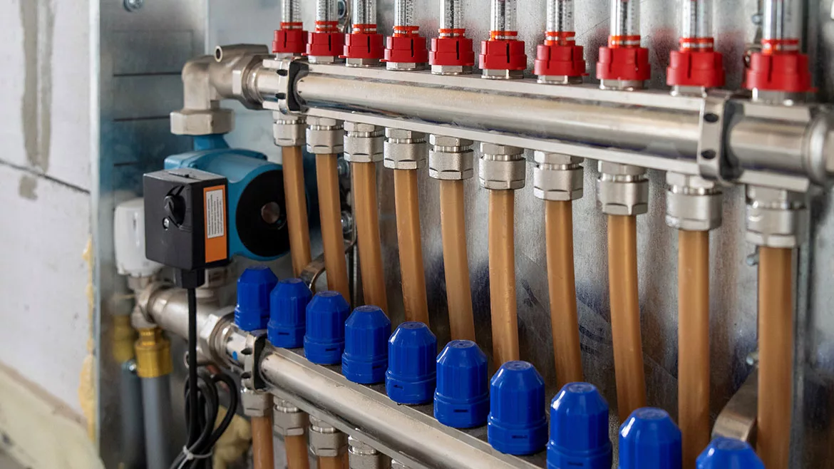
One of the simplest techniques for connecting multiple heat emitters is called homerun system. This approach uses two runs of small flexible tubing (i.e., PEX, PEX-AL-PEX, PERT) to each heat emitter, one for supply and the other for return. In North America, the most common tube size is 1/2-inch. However, with proper design and the right type of heat emitter, it’s possible to use 3/8-inch tubing - provided comparable fittings are available for both the manifold and heat emitter connections.
Figure 1 shows the “classic” layout of a homerun system.
FIGURE 1
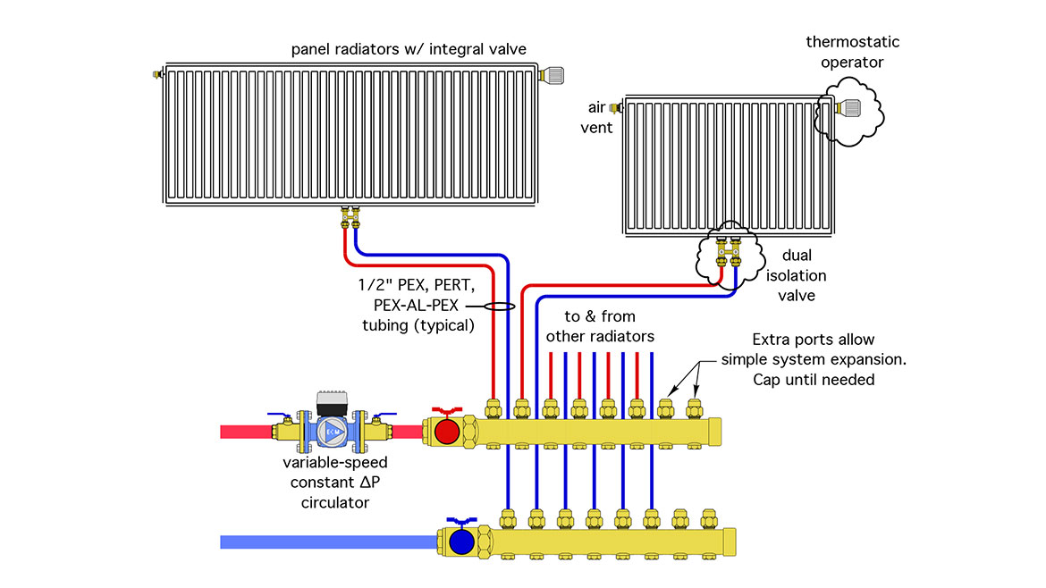
This configuration uses a single manifold station - the same as used with floor heating systems - as the origin and terminus for each homerun circuit. Each panel radiator is equipped with a valve fitted with a thermostatic operator. This allows each radiator to be independently controlled. Each radiator also has a dual isolation valve, which is an assembly of two ball valves and unions that connect to the base of panel radiators having supply and return connections spaced 50mm (2”) apart. By closing the two ball valve, each radiator can be isolated from the remainder of the system if necessary.
“There are situations where the heat emitters are widely dispersed within a building. A standard homerun system could work, but it often requires a lot of tubing when all the circuits start and end at a single manifold station.”
Although not mandatory, I like to specify manifold stations with at least one extra set of ports beyond those needed for the initial system configuration. These extra ports allow for simple expansion of the distribution system in the future. The extra ports can be capped until needed.
A variable-speed pressure-regulated circulator set for constant ∆P mode provides flow. It automatically adjusts speed to maintain a constant differential pressure as the radiator valves open, close, or modulate flow.
The supply and return piping for the manifold station could lead back to a low flow resistance boiler, a buffer tank or a hydraulic separator. Any heat source capable of producing the water temperature needed by the heat emitters at design load can be used.
In summary, the system in figure 1 is a simple, scalable, and from my perspective, an “elegant” design. Although panel radiators equipped with TRVs are shown, homerun systems can serve baseboard, cast-iron radiators, radiant floor, wall or ceiling panels, or various combinations of these heat emitters.
Spread it out
There are situations where the heat emitters are widely dispersed within a building. A standard homerun system, like the one shown in figure 2 could work, but it often requires a lot of tubing when all the circuits start and end at a single manifold station. It can also require lots of nominal 3/4” holes drilled through floor joists to route that tubing.
FIGURE 2
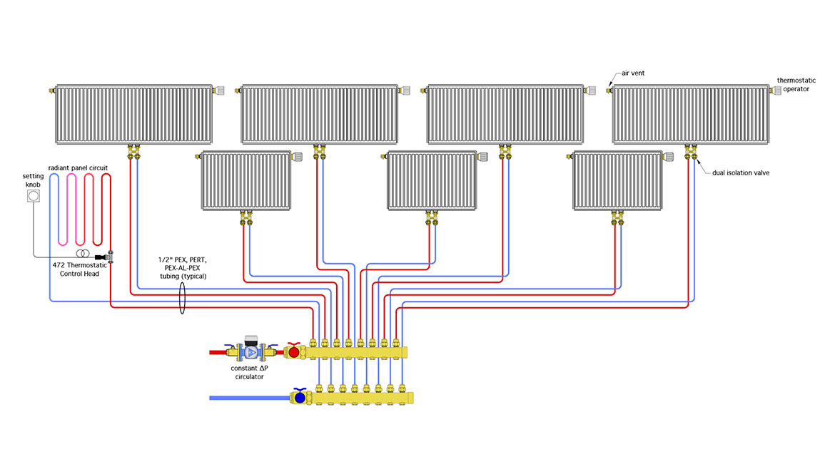
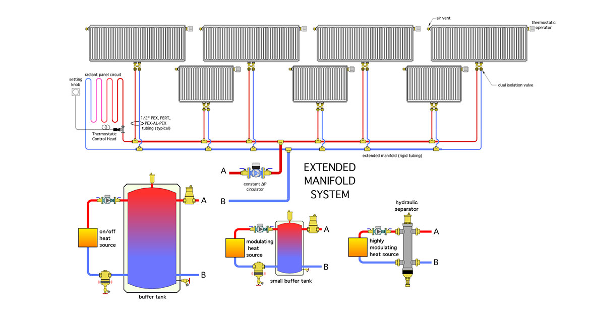
A variation on the homerun concept is what I call an “extended manifold” system. Figure 3 shows an extended manifold serving the same array of heat emitters as in figure 2.
FIGURE 3
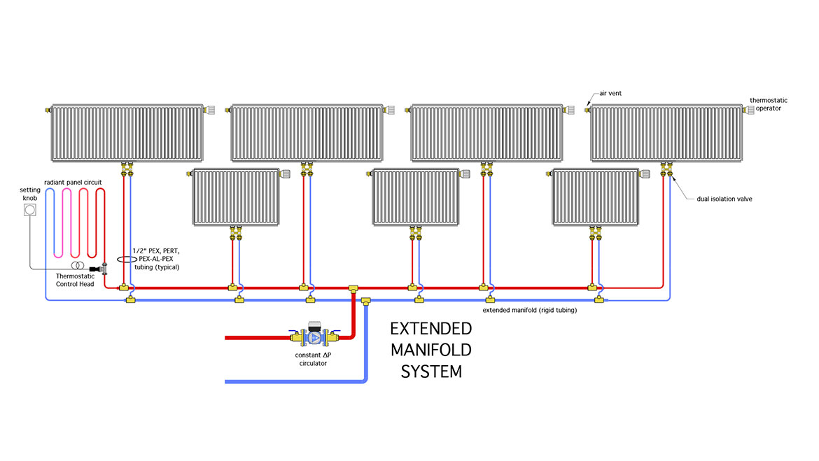
This approach uses straight pipe combined with reducer tees to divide flow among the heat emitters. The straight pipe that forms the extended manifold is typically copper, but could be other materials such as PEX, or PP-R.
When installed in a basement the extended manifold piping could be fastened to the underside of the floor framing, or along a main girder. The goal is to minimize the number of elbows required, while keeping the manifold piping close to the location of the heat emitters.
Ideally, the two tees that connect the extended manifold piping to the heat source can be located so that approximately equal flow would go in each direction. This reduces the flow rate in each half of the distribution system, which often eliminates any need to step down the pipe size. It also makes the system easier to balance.
Each reducing tee on the extended manifold transitions to 1/2” PEX, PEX-AL-PEX, or PERT tubing. The latter then runs along floor framing and pops up through the subfloor under the heat emitter.
Figure 4 shows an example of 3/4” copper tubing serving as the extended manifold, along with reducer tees that provide a take off point for 1/2” PEX-AL-PEX tubing that supplies a panel radiator.
FIGURE 4

In this project, the 3/4” x 3/4” x 1/2” copper press tees transition to a short length of 1/2” copper that’s soldered to a transition fitting for 1/2” PEX-AL-PEX tubing. The 3/4” copper is held up by supports that allow for expansion and contraction. The lower tube is offset horizontally by 1.5” to prevent interference with the upper tube.
A variable-speed pressure-regulated circulator provides all flow for the distribution system. If thermostat radiator valves are used on the heat emitters the circulator can operate 24/7 during the heating season, automatically adjusting its speed based on the status of the thermostatic radiator valves. When the flow velocity in the extended manifold piping is low (under 2 feet per second) the circulator can be set for constant differential pressure control. If the flow velocity is higher, or if the extended manifold is not connected near its midpoint as shown in figure 3, the circulator should be set for proportional differential pressure control.
A system similar to that shown in figures 3, and providing a design heating load of 35,000 Btu/hr, was powered by a small variable-speed pressure-regulated circulator that only required 44 watts at full speed, and typically operates between 20 and 30 watts of power input. Assuming electricity cost $0.20/kwhr, and that the circulator operates at an average power input of 30 watts, it would only cost about $0.15 to run the circulator for 24 hours.
When low thermal mass heat emitters such as panel radiators or fin-tube baseboard are used, along with an on/off heat source, a buffer tank should be used to interface the distribution system with the heat source. The size of the buffer tank should allow the heat source to operate for a minimum of 10 minutes with minimal if any load from the heat emitters.
When a modulating heat source is used, the size of the buffer tank can be relatively small; perhaps 15-25 gallons. If the heat source has a very wide range of modulation, a hydraulic separator could be used in lieu of a buffer tank. The buffer tanks or the hydraulic separator prevent the heat source circulator from interfering with the variable-speed distribution circulator. The hydraulic separator also provides air, dirt and magnetic particle separation for the system. If a buffer tank is used, I recommend installing a microbubble air separator and a magnetic dirt separator. Figure 5 shows these interface options.
FIGURE 5
Hydronic distribution systems don’t have to be complex to be clever. A homerun system, or the “extended manifold” variation, are easy to construct, scalable to meet project requirements, and highly efficient in terms of circulator power requirements. They allow each heat emitter to serve as an independent zone without the need for multiple thermostats, the associated low-voltage wiring, batteries, apps, or the internet. Sometimes simple is elegant…
Looking for a reprint of this article?
From high-res PDFs to custom plaques, order your copy today!


