Renewable Heating Design | John Siegenthaler
Balancing high- and low- mass heat emitters to prevent temperature "droop"
Some hydronic heating systems use slab-on-grade floor heating combined with an air handler or fan-coils in other areas of a building. This approach is also used for heated basement floors combined with a “hydro-air” delivery system for the main living areas.
In many of these systems, the air handler or fan-coils are sized for higher water temperatures compared to the slab-on-grade floor heating circuits. In systems using conventional boilers, the higher water temperature was often in the range of 150-180 ºF at design load. This water temperature was supplied directly from the boiler. A mixing assembly of some type (mixing valve, variable speed injection circulator, etc.) was used to create a lower water temperature for the floor heating circuits.
When only the air handler is operating, the boiler, the coil in the air handler and the fluid in the circuit connecting them reach a thermal equilibrium conditions very quickly, a few minutes at most. Assuming the high limit controller on the boiler is set high enough, the water temperature quickly settles to a value where the rate of heat input from the boiler equals the rate of heat output from the air handler’s coil.
When the heated slab is the only active load and operating at a steady state or near steady state conditions, a similar thermal equilibrium condition is maintained.
Unsteady situations: Although most hydronic systems are designed with the assumption of steady state operation those conditions seldom exist. During most of their operating time, the heat emitters are either warming up or cooling off, and so are the other components and fluid in the system. These “transient” conditions can quickly lead to unexpected operation conditions, especially when the system includes both high thermal mass and lower thermal mass heat emitters.
Consider a system that combines a 2,000 ft2 by 4-inch thick heated slab on the first floor with a 2-ton (24,000 Btu/hr) rated air handler on the upper floor. The system’s heat source is sized to handle the design load heat dissipation rate assuming all heat emitters are operating simultaneously.
Assume the slab has been “coasting” for a few hours following a thermostat setback. During that time, its temperature has dropped 10 ºF. Meanwhile, the air handler has been operating and keeping its associated space comfortable.
At some point, the owner turns up the thermostat for the slab-on-grade zone while the air handler continues to operate. Within a minute or two, the air temperature leaving the air handler drops significantly - even though the heat source is operating continuously.
This sudden decrease in leaving air temperature is caused by the thermal mass of the cool floor slab absorbing heat. Think of that slab as a “thermal sponge;” that’s now very “thirty” for Btus. Bringing the slab online under that condition allows it to soak up heat at a rate that could easily be 1.5 to 2 times higher than under steady state design load conditions. That high rate of heat absorption will immediately cause the system to seek a new thermal equilibrium condition, which can only be achieved at a much lower system temperature.
As time passes, and the slab slowly warms, the water temperature leaving the heat source gradually increases, and so does the air temperature leaving the air handler. Given sufficient time (perhaps several hours), the air temperature leaving the air handler is back to normal.
That condition is going to reoccur every time the slab has to “accelerate” from a lower temperature back to a steady state condition. It’s definitely going to lead to complaints and callbacks.
Mixed masses: Consider the four zone system shown in figure 1.
FIGURE 1
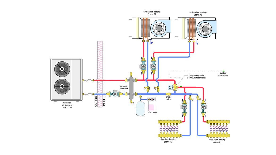
Image courtesy of John Siegenthaler
Two zones are low mass air handlers that require 120 ºF supply water temperature whenever they are operating. This is necessary to ensure acceptable discharge air temperatures. The other two zones are high thermal mass heated floor slabs that require 105 ºF supply temperature at design load.
The heat pump controls are set to produce 120 ºF leaving water temperature when the heat pump is called to operate. A 3-way motorized mixing valve is used to lower the water temperature for the slab zones.
The low mass heat emitter zone operates fine when the floor slabs are not calling for heat.
The high mass slabs also provide good performance when they are the only active zones.
However, when slab and air handlers are called to operate simultaneously, the leaving water temperature from the heat pump drops rapidly and remains well below the 120 ºF needed for acceptable discharge temperature from the air handlers. This condition persists until the slab zones are both off. This “droop” is especially noticeable when the slabs are recovering from a thermostat setback -- or even worse -- from a cold start condition.
This is all attributable to thermal equilibrium. The high thermal mass and low water temperature design of the slabs “dominates” the situation. The water temperature in the system is only going to warm up to where the rate of heat output from the heat pump matches the ability of the system to dissipate heat. If that happens to occur at, say, 95 or 101 ºF, that’s the water temperature supplied to the air handlers. This is basic thermodynamics at work.
Can we compromise?
One way to avoid this “droop” condition is to ensure that both of following prerequisites are present:
- The system’s heat source is sized large enough to handle the dissipation rate of all heat emitters under design load conditions, and…
- The high mass zones are operated as “steadily” as possible using techniques such as outdoor reset control of water temperature, and very minimal if any thermostat setback.
In situations where both of these prerequisites cannot be met, there is technique that can help minimize undesirable temperature droop due to transient operation. It’s based on “sharing” the heat source’s output between the high and low thermal mass loads. The idea is to devote the full output of the heat source to one load for a period of perhaps 10-15 minutes, and then shift all output to the other load for a similar (although not necessarily equal) time.
The key component that enables this time-sharing operation is a repeat cycle time delay relay (RCTDR), such as the one shown in figure 2.
FIGURE 2
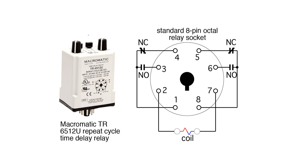
Image courtesy of John Siegenthaler
This is a double-pole / double throw (DPDT) relay with a 24VAC coil. It mounts into a standard 8 pin octal socket. This particular model costs in the range of $100, and has a wide range of time delay range settings such as 3-30 minutes, or 0.5 to 5 hours.
When the coil is powered on, the relay contacts activate (e.g., the normally-open contacts close and the normally-closed contacts open). This “state 1” mode continues until the “state 1” time delay expires, at which point the contacts reverse and the relay enters its “state 2” mode. The dials at the top of this relay are used to set the “state 1” time delay and the “state 2” times delay, which can be the same or different. For example, the state 1 delay could be set for 10 minutes, and the state 2 delay set for 15 minutes. One dial is also used to select the range of time delays.
This back and forth “toggling” repeats as long as the coil of the RCTDR remains powered. When power is removed, the relay resets and the repeat cycle action reinitiates the next time 24VAC is applied to the coil.
Figure 3 shows how this RCTDR, along with some other 24 VAC 3PDT relays can be applied in a system such as shown in figure 1.
FIGURE 3
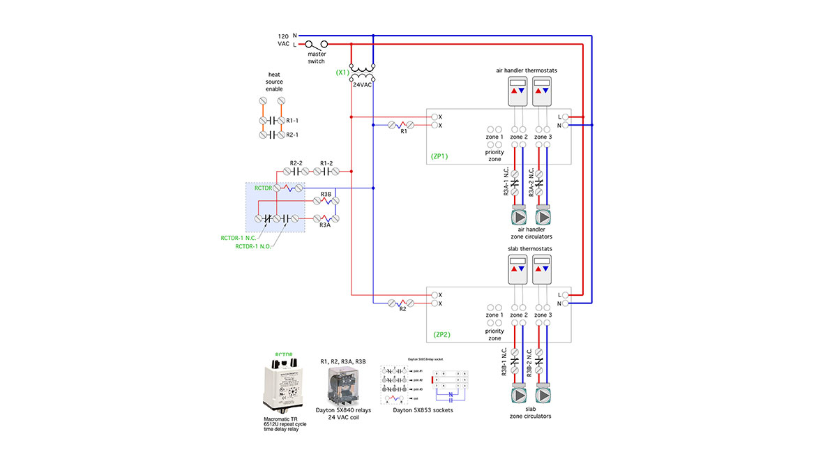
Image courtesy of John Siegenthaler
This system uses two multi-zone controllers, one for the air handler zones and the other for the slab zones. When there’s a call for one or both air handlers to operate, their associated circulators are turned on, (e.g., 120 VAC passes through the normally-closed relay contacts labelled R3A-1 NC and R3A-2 NC). The (X X) relay contact in the multi-zone controller closes to power the coil of relay (R1). Relay contact (R1-1) closes to enable heat source operation. The heat source circulator is assumed to be turned on by the heat source.
A similar sequence is used when one or both of the slab zones are called to operate. 120 VAC passes through normally-closed relay contacts (R3B-1 NC) and (R3B-2 NC) to operate the zone circulators.
If either of the air handler zones is called to operate at the same time as either of the slab zones, relay contacts (R1-2) and (R2-2), which are wired in series, are both closed, allowing 24VAC to energize the coil of the repeat cycle time delay relay (RCTDR). That relay begins its toggling action when its normally-open contact closes 24VAC powers on the coil of relay R3A. This causes the normally-closed contacts (R3A-1NC) and (R3A-2NC) to open, breaking line voltage to both air handler circulators. The heat source and its associated circulator remain on. The full output of the heat source is now available to the slab zones.
The system water temperature will either climb to a value established by thermal equilibrium between the slab heat emitter and the heat pump, or to the target temperature of the 3-way mixing valve - whichever temperature is lower.
Although most hydronic systems are designed with the assumption of steady state operation those conditions seldom exist. During most of their operating time, the heat emitters are either warming up or cooling off, and so are the other components and fluid in the system.
This mode of operation continues until the “state 1” set time delay of the (RCTDR) expires. When that occurs the (RCTDR) reverses it contacts, turning off the slab zones and turning on the air handler zones. This mode continues until the “state 2” time delay expires, at which point the entire sequence repeats.
If at any time only the slab zone(s) or only the air handler zone(s) are operating, the (RCTDR) remains unpowered, and no toggling action occurs. It’s not necessary to share the heat output of the boiler under these conditions.
Don’t let perfect be the enemy of good: This “time sharing” control concept isn’t an ideal solution because it doesn’t allow all the loads to operate simultaneously. Instead, it shares heat delivery over time and across all the heat emitters in the system. It prevents air handlers or fan-coils from operating with discharge air temperatures much lower than expected due to the simultaneous operation of high thermal mass/low temperature heat emitters. It leverages the fact that periodic disruption of heat input to high thermal mass emitters, for periods lasting from a few minutes to perhaps an hour or two, are usually imperceptible to occupants.
This technique can be designed into new systems that can’t meet the previously discussed prerequisite operations conditions. It can also be used as a way to correct the temperature “droop” issue on existing system that used both low thermal mass and high thermal mass heat emitters. Park it in your design toolbox and pull it out when needed.
Looking for a reprint of this article?
From high-res PDFs to custom plaques, order your copy today!


