John Siegenthaler: Modifying high-temperature distribution systems for lower-temperature operation — part two
Part two of a series

In last month’s “Heating with Renewable Energy” column we discussed how to size supplemental heat emitters that allow the supply water temperature to an existing distribution system to be reduced.
The next step is to pipe those supplemental heat emitters into the existing system. As with most things hydronic, there are multiple approaches, and the “best” approach for each installation has to consider cost, aesthetics, access to the existing piping, available wall space and the goal of how the overall system will operate based on existing or newly created zones. We’ll look at basic concepts that can be tailored to individual system needs.
Many residential hydronic systems have finned-tube baseboards connected in series or “split-series” circuits, as shown in Figure 1.
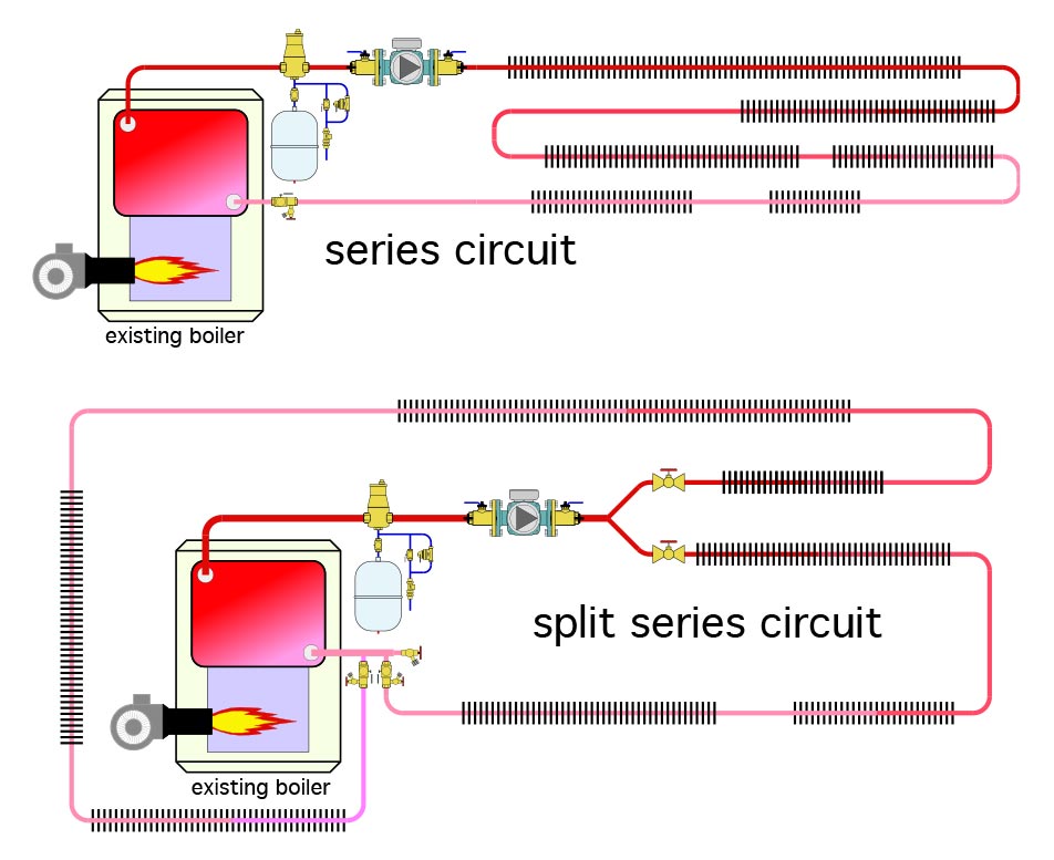 Figure 1
When heat emitters will be added to a system using series or split-series connected baseboards, they should not be simply cut into the series circuit. Doing so could substantially increase the flow resistance of that circuit, which will reduce flow rate assuming the same circulator is used. Adding heat emitters in series also increases the temperature drop of the circuit. This reduces the heat output of heat emitters near the end of the circuit, especially when the supply temperature to that circuit is lowered.
The preferred “make-over” of the series loop system is to make strategic cuts into the circuit where it is easiest to access, and reconnect the cut segments back into a parallel distribution system.
These cuts could make each room a separate parallel circuit. They might also make a group of two rooms into a new zone.
One of the easiest ways to divide an existing series loop or split series distribution system into multiple parallel circuits is by creating a homerun distribution system. Each heat emitter, or grouping of an existing heat emitter and a supplemental heat emitter, is supplied by a separate circuit of PEX, PERT or PEX-AL-PEX tubing. This tubing is easy to route through cavities or along framing. The homerun circuits begin and end at a manifold station. This concept for converting a series baseboard system into a homerun system is shown in Figure 2.
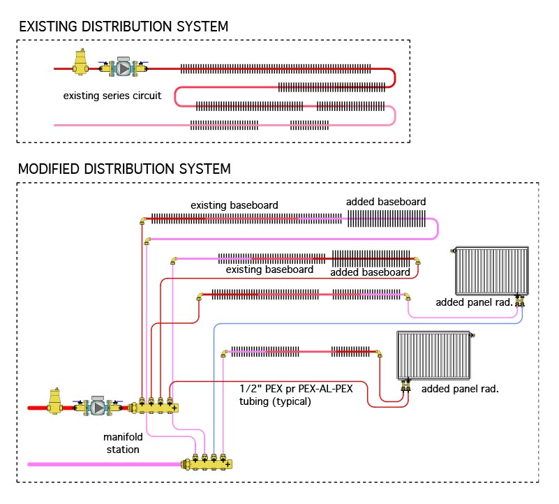 Figure 2
In this situation, the existing series circuit was divided into four branch circuits. Supplemental heat emitters were added to each of these circuits. Two of the circuits received additional finned-tube baseboard, and the other two received panel radiators. These selections are only to illustrate that multiple types of supplemental heat emitters can be used depending on available wall space, budget, and aesthetic preferences.
In some branch circuits, the supplemental heat emitters were added upstream of the existing baseboard. In others, they were added downstream of the existing baseboard. The choice depends on the available wall space, and placement of the existing baseboard within each room.Designers should estimate the water temperature in the circuit where the supplemental heat emitter will be placed, and size it accordingly.
The 3/4-inch copper tubing in the existing circuit was cut at locations that preserved a reasonable amount of existing copper tubing, but also allow convenient transition to 1/2-inch PEX, PERT or PEX-AL-PEX tubing. Adapter fittings to transition from 3/4-inch copper to 1/2-inch PEX or PEX-AL-PEX tubing are readily available from several suppliers. Some examples are shown in Figure 3.
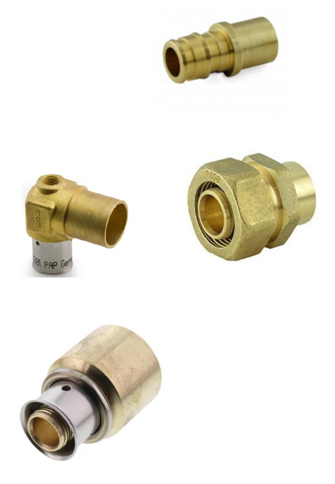 Figure 3
The 1/2-inch PEX, PERT or PEX-AL-PEX supplies and returns are routed back to a manifold station. That manifold may be equipped with individual circuit balancing valves that allows the flow rate through each of the new branch circuits to be adjusted if necessary. If a non-valved manifold is used flow balancing valves should be installed in each branch circuit.
The four branch circuits shown in Figure 2 operate simultaneously (e.g., they are not configured as individual zones). As such, this distribution system presents a constant flow resistance. Due to the parallel versus series configuration, that flow resistance will typically be lower than that of the original series circuit. This should be verified by calculating the head loss or pressure drop of the path with the greatest flow resistance using standard hydronic circuit analysis methods.
If the head loss and total flow rate through the four circuits is comparable to the flow and head loss of the existing series circuit, the same circulator can be used. If the flow resistance is significantly less, consider replacing the existing circulator with an appropriately sized high efficiency (ECM) circulator, set for constant speed operation.
One big advantage of a parallel distribution system is that it supplies water at approximately the same temperature to each branch circuit. This is likely to boost the heat output of some existing baseboards that were previously located near the end of the series circuit.
Creating new zones
Another advantage of parallel distribution systems is the ease of creating multiple zones. If the existing series circuit is converted to multiple branches, each of those branches can be equipped with a thermostatic radiator valve. These non-electric valves automatically modulate to vary the flow rate in each branch in response to the room temperature. As room temperature begins to drop, the thermostatic valve opens to increases flow through that branch circuit, and vice versa.
Thermostatic radiator valves are available in several configurations. One configuration, known as an angle pattern supply valve, allows the valve to be mounted on the inlet to a finned-tube baseboard. The thermostatic actuator of the valve projects out through a hole in the end cap of the baseboard with its shaft parallel to the wall. Heated water enters the port of the valve facing the floor, makes a 90-degree turn as it passes through the valve, and flows into the baseboard element. The other end of the finned-tube element can be equipped with another transition adapter (straight or 90-degree) to convert from 3/4-inch copper to 1/2-inch PEX or PEX-AL-PEX.
Another type of thermostatic radiator valve allows the valve body and actuator to be mounted within the baseboard enclosure, while the adjustment knob is mounted at normal thermostat height on the wall. The adjustment knob connects to the actuator using a capillary tube. It’s also possible to use panel radiators with built-in thermostatic radiator valves.
Figure 4 shows how the distribution system can be modified using thermostatic radiator valves to create a distribution system with four independently controlled zones. This adds flexibility for adjusting interior comfort conditions far beyond that of the original series loop system.
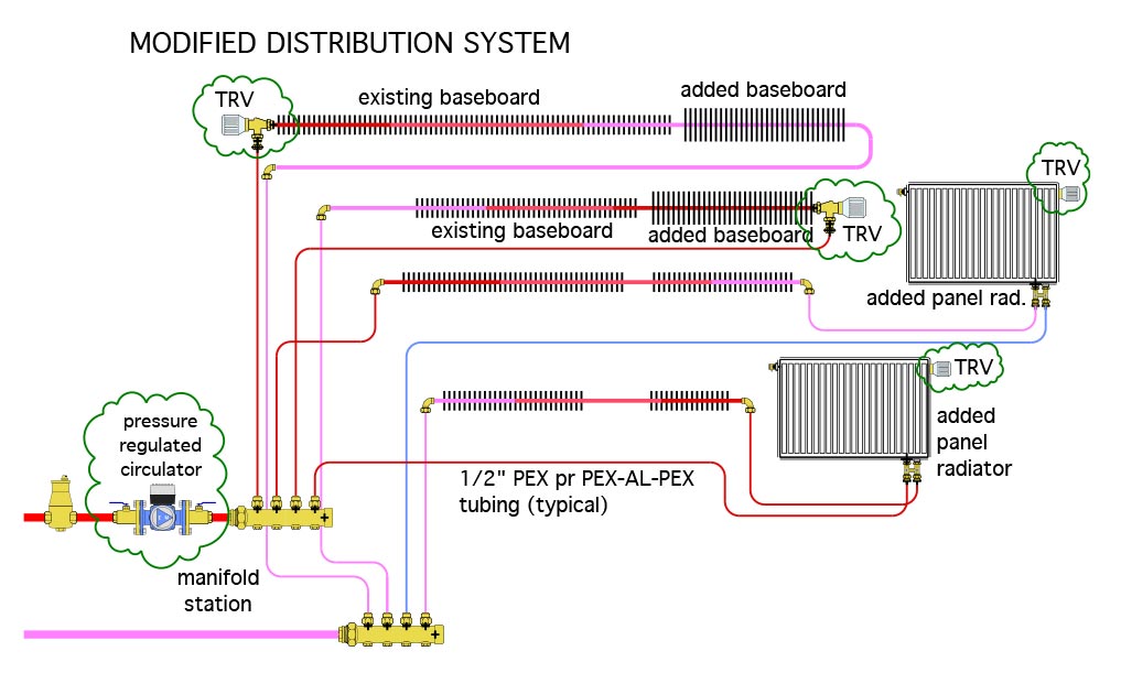 Figure 4
Another possibility is to install a low voltage (24 VAC) manifold valve actuator on each circuit valve at the manifold station. These actuators are wired to four new thermostats, one for each zone. This option is shown in Figure 5.
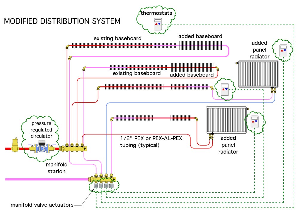 Figure 5
The systems shown in Figures 4 and 5 both use valves for zoning. In both cases, the original circulator has been replaced with a variable speed pressure regulated circulator that automatically adjusts its speed and power input as the valves open, close or modulate flow. This helps stabilize the differential pressure across the manifold station, and helps maintain stable flow rates within in zone circuit regardless of what other zones are operating.
Design guidelines
The modifications shown to convert a series baseboard circuit into parallel branch circuits are just a few of many possibilities. Each conversion situation must consider the exact layout of the existing heat emitters, and the practicality of modifying the system into parallel branches. Designers should follow these guidelines:
- Determine what type of supplemental heat emitter will be used in each room and where it will be located before modifying the piping;
- From the standpoint of cost and installation time, it’s best to use as much of the existing piping as possible;
- Consider the benefit versus cost of creating new zones when modifying the existing system. For example, if two bedrooms are typically maintained at the same temperature, and the existing system has accomplished this, it’s best to keep these two bedrooms together on the same zone, after adding the necessary supplemental heat emitters. However, if the piping modifications to do so are comparable in cost/time to creating two independent zones, then the latter is arguably a better choice;
- Once all the supplemental heat emitters have been selected and the proposed modifications to the distribution system have been sketched, run a flow and head loss analysis for the modified system. This is used to confirm sufficient flow to each branch and determine a suitable circulator for the modified system; and
- If the existing conventional boiler will be retained for use as a backup heat source for the low temperature system, ensure the boiler is protected against sustained flue gas condensation by installing a thermostatic mixing valve near the boiler as shown in Figure 6.
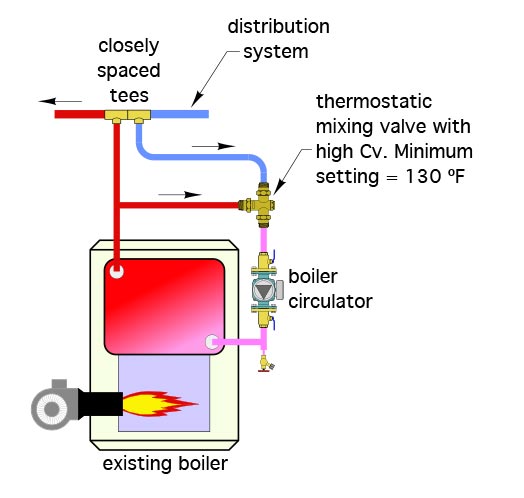 Figure 6
The future of hydronic heating is low water temperatures, with increased use of heat pumps as the primary heat source. Use the guidelines we’ve discussed in this column as well as in part one to transition legacy distribution system into full compatibility with this progression, allowing them to deliver superior comfort for decades to come.
Looking for a reprint of this article?
From high-res PDFs to custom plaques, order your copy today!


