Hydronics Workshop | John Siegenthaler
Injection mixing revisited (part 2)
Advanced ways injection mixing can manage temperature, protect equipment, and stabilize modern hydronic systems.
Last month, we reviewed the basics injection mixing. It’s a method for controlling water temperatures by regulating the flow of heated water “injected” into a circulating distribution system, while simultaneously removing an equal flow of cooler water from that distribution system. Any method that controls the rate of injection flow also controls the rate of heat transfer into the distribution system.
Many North American systems have used a variable speed circulator as the injection control device. However, 2-way modulating valves operated by thermostatic actuators or motorized actuators can also serve this purpose.
This month, we’ll look at some unique applications of injection mixing including:
- Regulating heat transfer through a heat exchanger
- Regulating the output temperature from a hydraulic separator
- Protecting a boiler from sustained flue gas condensation
- Regulating heat transfer from an outdoor wood-fired furnace
Throttling a heat exchanger
Suppose you want to set up a brazed plate heat exchanger to supply heat to the antifreeze solution in the heating circuits of a garage floor slab. The antifreeze is needed because the project is in a cold location, and the garage will only be occasionally heated.
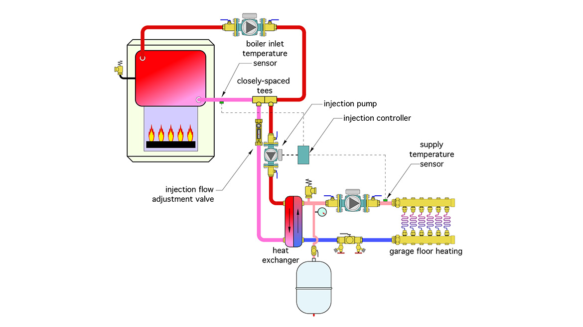
When operating, the system requires a supply temperature of 115 ºF. The boiler also needs to be protected against sustained flue gas condensation. I suggest the setup shown in figure 1.
FIGURE 1
Drawing courtesy of John Siegenthaler
The injection pump controls the flow rate supplied to the primary side of the heat exchanger. Feedback to the injection controller comes from the supply temperature sensor in the circuit supplied from the secondary side of the heat exchanger. The injection pump is hydraulically isolated from the boiler loop circulator by a pair of closely spaced tees. I’ve heated my garage floor using this configuration for the last 24 years. Works great.
Taming a “wild” heat source
Figure 2 shows a system discussed in my May 2024 Hydronics Workshop column. It was designed for adding an air-to-water heat pump to a system currently supplied from an outdoor wood-fired heater.
FIGURE 2

Drawing courtesy of John Siegenthaler
In this system, the circulator in the outdoor heater, and the circulator supplying the floor heating circuits run continuously.
A heat exchanger is used to separate the open loop piping of the outdoor heater from the remainder of the system, which operates as a closed loop.
The outdoor heater is the first stage heat source, with the air-to-water heat pump operating as second stage heat source. As such, it’s possible for both to run at the same time.
A variable speed injection circulator regulates the rate of heat transfer from the heat exchanger to the hydraulic separator. The goal is to maintain a target supply water temperature to a heated floor slab. That temperature is based on outdoor reset control, which extends the time over which the wood-fired heater can supply the floor as the fire is burning down.
Notice the placement of the sensor labelled “boiler return temp. sensor.” It’s on the pipe leaving the primary side of the heat exchanger. In this application, that sensor keeps the injection controller from operating the injection pump until the water leaving the heat exchanger is above some minimum setpoint temperature. This prevents inadvertent heat transfer back to the outdoor heater when it’s not operating or operating at a very low water temperature. It also prevents heat transfer back to the outdoor unit if the heat pump is operating simultaneously with the wood-fired heater.
Doubling up
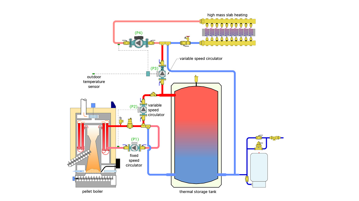
The pellet-fired boiler system in figure 3 uses two variable speed injection circulators: one to protect the boiler against flue gas condensation, and the other to inject heat from the thermal storage tank into the distribution loop.
FIGURE 3
Drawing courtesy of John Siegenthaler
Circulator (P1) is a fixed speed circulator that operates whenever the pellet boiler is on. It delivers heated water to the closely spaced tees. Circulator (P2) is a variable-speed temperature-controlled circulator. It monitors the boiler inlet temperature and controls its speed to keep the boiler inlet temperature at or above 130 ºF. Circulator (P2) is creating a mixing point at the tee where cooler water from the lower portion of the thermal storage tank meets with hot water from the boiler.
Another injection pump (P3) shuttles hot water from the upper portion of the thermal storage tank into the distribution system. The injection controller operates (P3) based on maintaining a target supply water temperature for the distribution system.
Either way
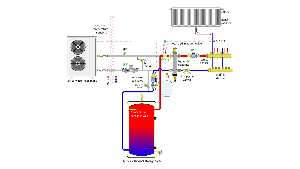
The system in figure 4 uses a high temperature R-290 air-to-water heat pump to supply heat to thermal storage tanks or directly to the heat load. The heat pump operates primarily when low cost “off-peak” electrical rates are in effect. During this time, the output of the heat pump is primarily routed to thermal storage. However, the system is capable of supplying heat directly to the heat emitters, if necessary, at any time to maintain comfort in the building.
FIGURE 4
Drawing courtesy of John Siegenthaler
This system has multiple operating modes:
- Heat pump adds heat to thermal storage
- Heat pump supplies heat to heat emitters
- Thermal storage supplies heat to heat emitters
Figure 4 shows the system in mode 3 (thermal storage supplies heat to heat emitters).
The thermal storage tank could be at a temperature much higher than needed by the heat emitters. Thus, some type of mixing is necessary.
One possibility is to control the speed of circulator (P2) using a 0-10 VDC or pulse width modulation (PWM) signal. There are circulators currently available in North America with 0-10 VDC inputs, and more are likely in the future. PWM control is more common in Europe at this time. This approach also requires a controller that can output a 0-10 VDC or PWM speed control signal based on maintaining a target supply water temperature.
The speed of (P2) determines the rate of hot water flow from the upper portion of the storage tank, through motorized valve (MV1), and into the hydraulic separator. The temperature sensor downstream of circulator (P3) provides feedback to the controller operating circulator (P2).
Another possibility is to operate circulator (P2) as a fixed speed circulator and control the injection flow into the hydraulic separator by modulating motorized valve (MV1).
A variable speed injection circulator regulates the rate of heat transfer from the heat exchanger to the hydraulic separator. The goal is to maintain a target supply water temperature to a heated floor slab.
Either approach is a form of injection mixing. There may even be a way to combine variable speed operation of the injection pump (P2) with modulation of the injection valve (MV1) for precise control of the supply water temperature while also minimizing circulator input power.
You can read more about the operation of the system in figure 4 in the October 2025 Hydronics Workshop column.
Learn it & apply it
Although injection mixing is more commonly used with conventional boilers supplying low temperature heat emitters, there are several other contemporary uses for this concept. It can be implemented using either a variable speed circulator or a modulating valve as the injection control device. If you design hydronic systems injection mixing is definitely a technique you should learn and apply.
I wish you and your family a happy and blessed Christmas.
Looking for a reprint of this article?
From high-res PDFs to custom plaques, order your copy today!


.jpg")