John Siegenthaler: Injection mixing combined with thermal storage
Many hydronic systems include thermal storage tanks.
Many hydronic systems include thermal storage tanks — especially systems with renewable energy heat sources. When the heat input is from an array of solar thermal collectors or a biomass boiler, it’s possible for the water temperature in those tanks to reach temperatures of 180°-200° F. Thermal storage tanks supplied by electric boilers operating on off-peak electricity can also reach these high temperatures by the end of the charging cycle.
A 500-gallon tank filled with 190° water contains a lot of heat. However, the usefulness of that heat depends on the supply temperature required by the heat emitters in the system. The lower the tank temperature can be while still meeting the heating load of the system, the more useful heat it delivers.
Aim low
One recommendation I’ve promoted for several years is that all hydronic heating systems should be designed to supply design-load output using a supply-water temperature no higher than 120°. This upper temperature limit is consistently attainable by most renewable heat sources such as solar collectors, air-to-water heat pumps, geothermal water-to-water heat pumps, and biomass boilers. It’s also complementary to systems using high-efficiency modulating/condensing boilers.
There are several heat emitter options that allow designers to assemble low-temperature heating distribution systems. They include floor, wall and ceiling radiant panels; panel radiators; low-temperature fan-coils; and even “low-temp” fin-tube baseboard.
Designers can also combine two or more types of low-temperature heat emitters in the same system. One example would be a heated slab-on-grade radiant panel on the first floor of a building with individually controlled panel radiators on the second floor.
The idea is to select a maximum supply water temperature for the entire system based on design load conditions, and then match the various heat emitters to the room loads based on their respective heat output rates at the selected supply temperature.
The combination of high-temperature water in thermal storage and low-temperature heat emitters necessitates some type of mixing assembly between these subsystems. There are several options including thermostatically actuated and motorized three-way mixing valves, or injection mixing using either a motorized valve or variable speed injection pump.
The latter is a technique that, while it’s been available for over 25 years and applied in many low-temperature systems supplied by conventional boilers, has not found frequent use in systems supplied by renewable energy heat sources. Many system designers immediately associate the need for mixing with mixing valves and are not familiar with variable-speed injection mixing as an option.
While mixing valves can certainly accomplish the intended task, there are scenarios where variable-speed injection mixing may be less expensive because it provides both fluid transport as well as mixing. This eliminates the need for a circulator in combination with a mixing valve.
Hot in, cool out
Injection mixing is simply a way to add hot water to a circulating hydronic distribution system while at the same time removing an equal amount of cooler water. Replacing cooler water with hotter water adds heat to the distribution system. When heat is added the rate of heat output from that distribution system increases. The faster the hotter water is exchanged with cooler water, the greater the rate of heat output.
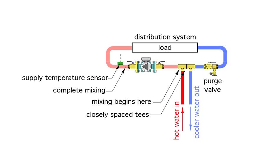
With injection mixing, the two fluid streams come together in a tee rather than inside a mixing valve. This fundamental concept is shown in Figure 1.
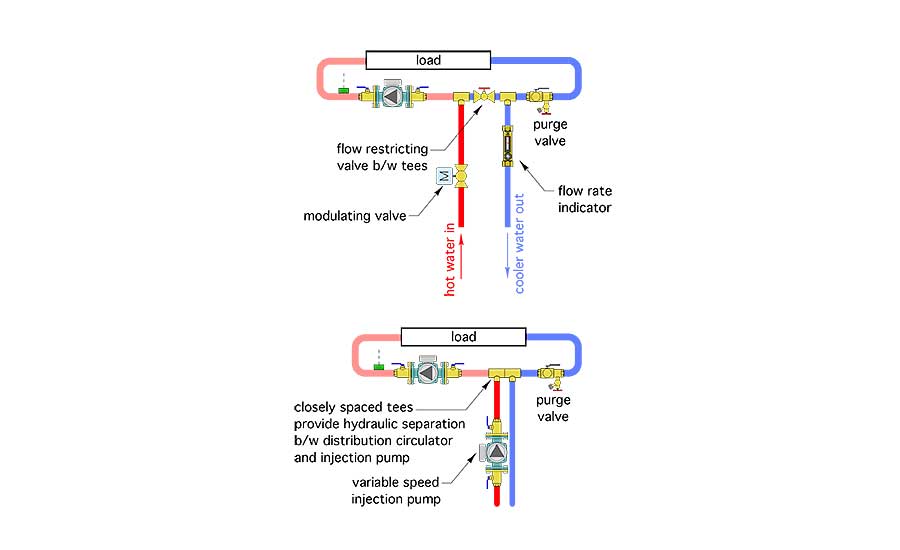
Any hardware assembly that can regulate the exchange of warmer water for cooler water is a potential means of injection mixing. Common hardware arrangements include a modulating two-way valve as well as with a variable speed pump. These are shown in Figure 2.
The temperature sensor that provides feedback on the supply water temperature to the distribution system should be located downstream of the distribution circulator. This allows the sensor to “feel” the final mixed temperature supplied to the heat emitters.
The math
The thermodynamics associated with injection mixing are simple and independent of the hardware being used. Furthermore, injection mixing is fully “scalable” from residential systems to large commercial systems where heat transfer rates can be several million Btu/h.
Figure 3 shows a typical piping detail for injection mixing using a variable-speed pump, along with formulas that govern the rate of heat transfer.

The variable-speed injection pump can be located in either of the two injection risers. It can push heated fluid into the distribution system or push cooler water from the distribution system back to the portion of the system where heat is generated or stored. The latter keeps the injection pump slightly cooler.
The two injection risers connect the heat source circuit to the distribution system. The closely spaced tees at these connections provide hydraulic separation between the variable speed injection pump and other circulators in the system. This is critically important since the variable-speed injection pump is often operating at a much lower speed than the other two circulators.
Hot water passes through the red injection riser shown in Figure 3 at a rate determined by the speed of the injection pump. Since the distribution system is completely filled, an equal flow rate of cooler water must flow from the distribution system through the other (blue) injection riser.
The hot water injected enters the downstream tee in the distribution system and mixes with a portion of the cooler fluid that has passed through — rather than out of — the upstream tee. These two fluid streams combine to determine the mixed fluid temperature supplied to the heat emitters.
The formulas shown in Figure 3 are all based on a balance of mass and thermal energy at the tee where the fluid streams combine.
Formula 1 can be used to calculate the rate of heat input to the distribution system if the injection flow rate, as well as the temperature of the fluid being injected, and the temperature of the fluid on the return side of the distribution system are known.
Formula 2 is just a rearrangement of Formula 1. It can be used to calculate the injection flow rate required to establish a specified rate of heat transfer into the distribution system.
Formula 3 can be used to calculate the mixed fluid temperature supplied to the heat emitters, at sensor (S1).
A distinct advantage of injection mixing is that the hardware regulating the mixing only has to handle the injection flow rate (fi), rather than the full distribution system flow rate (fd). If the heated water being injected is significantly hotter than the temperature of the water returning from the heat emitters, the injection flow rate can be quite small relative to the distribution flow rate.
For example: Assume water at 180° is available from the heat source, and that the distribution system serves radiant floor heating circuits that operate with a supply water temperature of 100° at design load conditions with a corresponding return water temperature of 85°. Also assume that the distribution system flow rate is 10 gpm. Under these conditions, the rate of heat dissipation by the distribution system is:

The required injection flow rate to transfer heat to the distribution system at this rate can be found using Formula 2 in Figure 3.
In this scenario, the injection flow rate is only about 16% of the distribution flow rate. Such a small flow rate could easily be handled by a small circulator and ½-inch injection riser piping.
The tank is not always hot
Situations in which high-temperature water is consistently available from the heat source, combined with a low-temperature distribution system, are ideal for injection mixing. However, such conditions aren’t always present when injecting from a thermal storage tank, especially one supplied by solar thermal collectors or a biomass boiler.
For example, a thermal storage tank supplied by solar thermal collectors might attain a temperature of 180° after a sunny or mild day, but might only be at 100° a couple of cloudy days later. A thermal storage tank supplied by a pellet boiler might reach 190° at the end of a boiler firing cycle, but could drop to a much lower temperature as heat is extracted, but before the boiler fires for the next charging cycle. The latter condition is desirable in that it allows for long boiler firing cycles which improve efficiency and reduce emissions.
These conditions are not a problem, provided that the injection flow rate can increase as the temperature of the water from the heat source decreases.
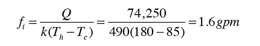
For example, we previously calculated an injection flow rate of only 1.6 gpm based on 180° water from the heat source. If the heat source could only supply 105° water, and the same 100° supply/85° return temperature were to be maintained in the distribution system, the required injection flow rate would be:
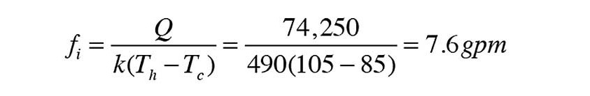
The same rate of heat transfer (74,250 Btu/h) can be maintained under these conditions, provided that the injection pump can provide a flow rate of 7.6 gpm through the injection risers.
The tank as a heat source
Figure 4 shows one way to configure a variable-speed injection pump in combination with a thermal storage tank.
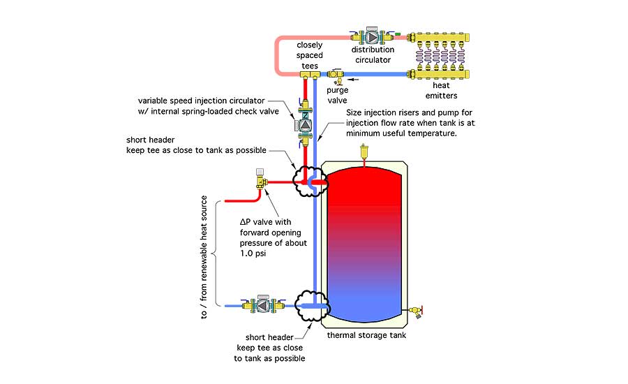
The thermal storage tank is set up in a “two-pipe” configuration. The piping supplying the load tees off from a short and generously sized header entering the upper side wall connection on the tank. Return flow from the load ties into a similar header at the lower sidewall connection. The combination of these short and generously sized headers, along with an extremely low dynamic pressure drop through the tank, provide adequate hydraulic separation between the heat source circulator and the variable speed injection pump.
The injection riser piping connects to the distribution system using closely spaced tees. These provide hydraulic separation between the variable speed injection pump and the distribution circulator.
A spring-loaded differential pressure valve with a forward opening pressure of about 1.0 psi is used to prevent unintentional flow through the heat source when the load is supplied from thermal storage and the heat source is off. This valve also prevents reverse thermosiphoning from the tank back through the heat source circuit.
Maintaining control
The controller operating the injection pump could be set up to provide a fixed supply temperature to the distribution system. It could also be set up to vary the supply temperature based on outdoor reset control. The latter is preferred because it allows the thermal storage tank to be discharged to lower temperatures under partial load conditions. Lower tank temperatures — provided they maintain adequate heat output from the distribution system — allow renewable heat source to operate at higher efficiency.
There are several low-cost controllers currently available that can vary the speed of wet-rotor circulators with permanent split capacitor (PSC) motors. They are appropriate for residential and light commercial applications where the injection circulator can be 1/6 hp or less.
However, the circulator landscape in North America is changing rapidly. Traditional hydronic circulators with PSC motors are being replaced by circulators with electronically commutated motors (ECMs). The controllers developed to vary the speed of circulators with PSC motors are not intended to be (and should not be) used with ECM-based circulators.
Some currently available wet-rotor circulators using electronically commutated motors can be operated at variable speeds using standard 2-10 VDC or 4-20 mA control signals. They range in size from residential to relatively large commercial models. Some of the latter can also be speed controlled directly from building automation systems using LONworks or BACnet protocols. There are also some ECM circulators currently available with built-in temperature sensing ability.
I suspect that more ECM-based circulators with the ability to monitor one or more temperature sensors and vary their speed based on maintaining a set point or reset-based supply temperature to a distribution system will be available shortly. The ability of such circulators to handle both mixing and fluid transport within a system — compared with valves that only provide the mixing function — should make them very price-competitive against other mixing and circulation options.
Put it to work
Everyone who designs modern hydronic system should be familiar with the concept of variable speed injection mixing. It fits well into the future of hydronic heating and cooling.
To read Siegenthaler’s article: “Injection mixing combined with thermal storage” in pdf form, please see here.
Looking for a reprint of this article?
From high-res PDFs to custom plaques, order your copy today!


