John Siegenthaler: 4-way versus 3-way motorized mixing valves
Which is the better choice, and why?
Although the market for gas-fired boilers continues to track toward those that can modulate and operate with sustained flue gas condensation, conventional boilers (e.g., those not designed to operate with sustained flue gas condensation) still represent a significant portion of the market. All oil-fired boilers fall into this category, as do copper tube boilers.
Some of these conventional boilers will be for higher temperature heat distribution systems, such as those using fin-tube baseboard or air handlers with minimally-sized coils. Some will also go into lower temperature systems serving radiant panels. The latter will require a mixing assembly between the boiler and low temperature heat emitters.
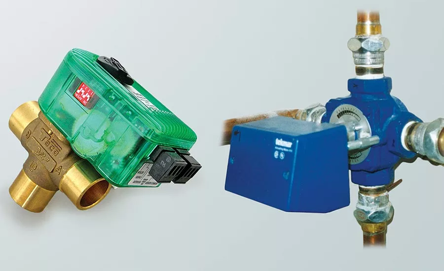
There are lots of choices for mixing assemblies. Two “classic” options are 3-way and 4-way motorized mixing valves. Both can provide the two critical functions when a conventional boiler is matched up with a low temperature distribution system:
- Control of the water temperature supplied to the heat emitters; and
- Preventing sustained flue gas condensation within the boiler.
Given that either mixing valve can provide these functions, it’s only natural to ponder which assembly is the better option. Let’s take a look.
When comparing 3-way and 4-way mixing valves, it’s good to understand their origin. Both date back to the days when essentially all hydronic heating systems were supplied by boilers that operated well above the dewpoint of their flue gases. Thus, both functions stated above were required.
Two mixing points
Providing control of supply water temperature as well as anti-condensation protection for the boiler requires two mixing points: One for the supply temperature and the other to regulated boiler inlet temperature. There is no way around this requirement.
Let me repeat: There is no way around this requirement!
Any proposed scheme that attempts to accomplish both functions using a single mixing point has a vulnerability that is sure to manifest itself under some operating condition.
The fundamental difference between systems using 3-way and 4-way mixing valves is where these two mixing points occur.
With a 3-way valve, the mixing point for the boiler anti-condensation function occurs in a tee, not inside the valve, as shown in Figure 1.
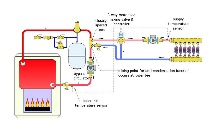
FIGURE 1
click to enlarge
Notice this system requires two circulators: One between the mixing valve and heat emitters, and another in the “bypass loop” near the boiler. Again, there is no way around this. No way to create two mixing points with a single circulator.
Why 4 instead of 3? 4-way motorized mixing valves were specifically designed to couple a conventional boiler having low head loss to a low temperature distribution system. Both mixing points occur within the 4-way valve body, as shown in Figure 2.
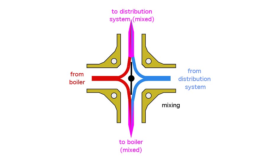
FIGURE 2
click to enlarge
The ideal piping scenario for a 4-way motorized mixing valve is shown in Figure 3.
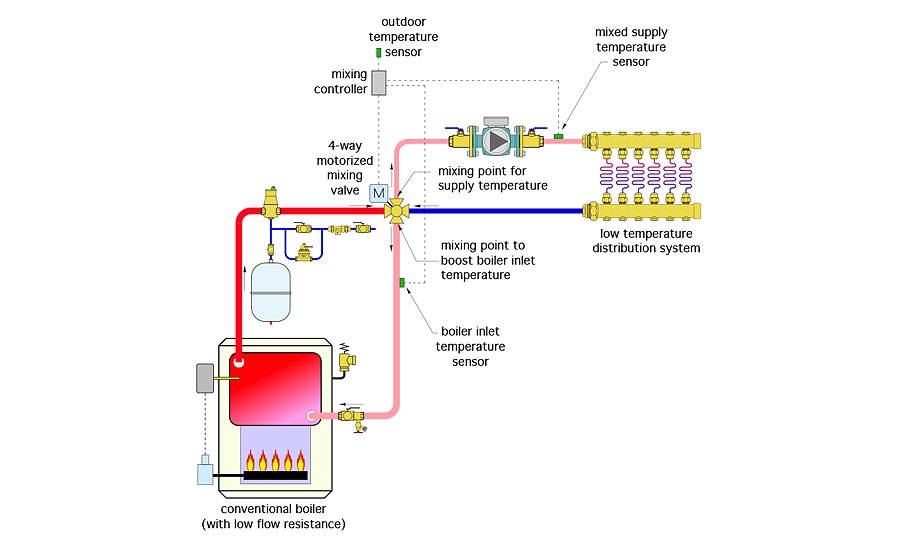
FIGURE 3
click to enlarge
Notice only one circulator is required in this system. Flow through the boiler is created by the momentum of the flow returning from the distribution system. That’s a major advantage. Not only does it reduce installation cost, it’s also likely to reduce the life cycle operating cost of the system by several hundred dollars.
However, there are two specific details that must be used to make this work correctly.
First, the boiler must have low flow resistance and relatively high thermal mass. Examples would include cast-iron sectional boilers and steel fire tube boilers, both of which are relatively insensitive to flow rate and have significant “self-buffering” characteristics. I don’t recommend this piping if a copper tube boiler will be used.
Second, the 4-way mixing valve should be installed as close to the boiler as possible. There should also be minimal and generously sized piping connecting the 4-way valve to the boiler. These details minimize the flow resistance through the boiler circuit enabling momentum to provide the necessary flow.
Watching the boiler inlet
The controller operating either a 3-way or 4-way motorized mixing valve in a system supplied by a conventional boiler requires a boiler inlet temperature sensor. The controller needs this sensor to “see” what’s happening at the boiler inlet. If the water returning to the boiler is below some setting (typically about 130° F for gas-fired boilers), the controller begins to close off flow to the distribution system. This directs flow entering the mixing valve from the boiler directly back to the boiler inlet, allowing the water temperature in the boiler to climb above the dewpoint of the flue gases as quickly as possible. Only when the boiler inlet is above this minimum temperature setting will the controller operate the mixing valve to allow full heat out to the rest of the system.
Controllers that operate motorized mixing valves prioritize boiler protection over supply water temperature. This seems to confuse some people, who think it limits heat transfer to the distribution system. It does not. The boiler is firing continuously as it is being protected against sustained flue gas condensation. It’s putting out heat at the maximum rate possible, and all of that heat is going to the distribution system.
No protection needed
3-way motorized mixing valves are well suited for use in low temperature distribution systems supplied from a thermal storage tank, as shown in Figure 4.
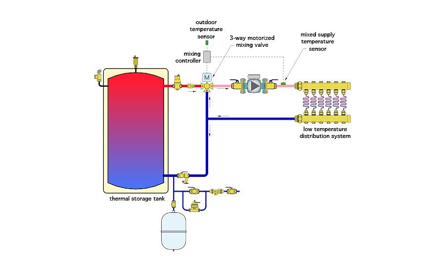
FIGURE 4
click to enlarge
There’s no point in using a 4-way valve in this situation because the thermal storage tank doesn’t need anti-condensation protection. However, in cases where the heat source burns any type of hydrocarbon fuel — and thus produces water vapor as a combustion byproduct — that boiler does need anti-condensation protection. Figure 5 shows an example where a cordwood gasification boiler supplies the thermal storage tank, which then supplies heat to a low temperature distribution system.
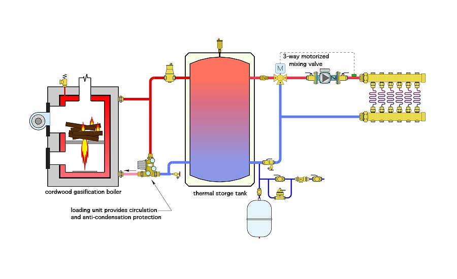
FIGURE 5
click to enlarge
this system, the boiler is protected against sustained flue gas condensation by a “loading unit.” This specialized device has European origins, and is currently available from at least two sources in North America. It combines a high flow capacity thermostatic mixing valve with a circulator. Although it could provide anti-condensation protection for conventional boilers operating on fossil fuels, it is most commonly used with residential scale pellet and cordwood gasification boilers. The 3-way motorized mixing valve on the right side of the thermal storage tank only regulates the water temperature supplied to the low temperature heat emitters. It plays no role in protecting the boiler against sustained flue gas condensation.
More details
There are several details that need to be present for either a 3-way or 4-way mixing valve to function as intended.
- Be sure the circulator is installed between the mixing valve and the heat emitters. Also be sure the valve body is oriented correctly. On “rotary” type 3-way motorized mixing valves, the mixed outlet port is one of the “run” ports of the valve body. On motorized 3-way ball valves, the mixed output port is the side port. The schematics in this article show the rotary type valve. Likewise, be sure the vane or spool inside a 4-way valve has the proper orientation relative to the piping connections. Installation instructions typically show how to position the valve’s shaft based on different piping configurations for the three ports.
- Be sure the supply water temperature sensor for the valve controller is mounted downstream of the circulator. Doing so ensures complete mixing of the hot and return water streams prior to the flow passing the sensor location. The controller can now respond to the “true” water temperature supplied to the heat emitters.
- Size the valves for a design flow pressure drop in the range of 0.5 to 1.0 psi. The design flow rate assumes that all zones in the distribution system are operating simultaneously.
- Never omit the actuator and controller from a “motorized” mixing valve. I’ve seen this done on several systems. There is no way for the valve to compensate for changes in entering flow rates or temperatures. It’s like removing the driver from a car and expecting that car to steer itself along a road that curves back and forth.
- Always check that the shaft of the valve turns easily and smoothly before attaching the actuator. Solder balls or other debris can jamb either type of valve.
- Although these valves are available with brass bodies and cast-iron bodies I prefer brass due to its corrosion resistance. In a perfectly closed system either type of valve body should be fine. However, I’ve witnessed jammed mixing valves with cast iron bodies due to oxygen egress into the system over time.
Some things don’t need to change
3-way and 4-way motorized mixing valves have been used in hundreds of thousands of heating systems over several decades, and all over the world. They’re currently available from several suppliers in North America.
When installed properly, they can provide stable and accurate control of the water temperature supplied to the heat emitters and protect conventional boilers from sustained flue gas condensation. In an era when plenty of new devices are introduced into the hydronics market every year, these valves remain classic and reliable.
Looking for a reprint of this article?
From high-res PDFs to custom plaques, order your copy today!


