Renewable Heating Design | John Siegenthaler
3-way diverter valves: Part 1
Digging into motorized 3-way diverter valves and actuator options.

Image courtesy of brebca / iStock / Getty Images Plus.
These valves have a common inlet port and two outlet ports, only one of which is open at a given time. They can be manually operated, such as the valve shown in Figure 1A, or operated by a 2-position motorized actuator, such as the valve shown in Figure 1B.
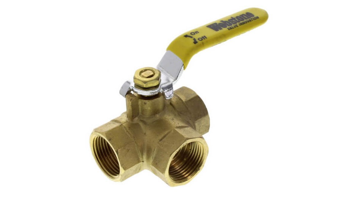 Image courtesy of Webstone
 Image courtesy of Belimo
Motorized 3-way diverter valves are common in systems that are expected to operate automatically. The typical configuration for these valves is the matching of a 3-way ball valve body with an electrically powered actuator capable of rotating the valve’s shaft through a nominal 90° of rotation.
Valve actuation
3-way diverter valves are available in a wide range of pipe sizes, Cv ratings, and with different actuator options.
The two most common actuator options are:
- Power open/power close; and
- Power open/spring-return close.
Both types of actuators use a small motor that drives a torque amplifying gear train. Using several intermeshed gears, the high speed and low torque of the actuator’s motor is covered in high torque/low speed rotation of the coupling that attaches to the valve shaft.
A power open/power close actuator requires a nominal voltage applied across specific terminals to open the valve, as well as across other terminals to close the valve. When the actuator reaches full travel in either position, the motor stops, but the actuator continues to draw a small amount of standby power (typically 2 to 5 watts).
A power open/spring return actuator only requires power to rotate the valve shaft in one direction. As this rotation occurs, a coil spring inside the actuator is wound up. When power is removed from the actuator, the mechanical torque created by the spring moves the valve’s spool to the other position.
One important operational difference between these actuator options is how they respond to a power interruption. When power is removed from a diverter valve with a spring-return actuator, the valve’s shaft always moves to its normal off position. When power is removed from a power open/power close actuator, the valve’s shaft stops wherever it is along its travel range. It is possible to adapt battery-operated power supplies to some power open/power close actuators to ensure the valve shaft goes to one of its limiting positions during a power outage.
Another difference is that a spring return actuator has a limit to the torque it can create. Value suppliers typically match the torque output of the actuator with the size and design of the valve it operates. However, if the system contains dirt, experiences corrosion or very infrequently operates the valve, the torque required to move the valve’s spool can increase. It’s possible that, under highly scaled conditions, the spring return actuator may not be able to move the valve’s spool across its full range of travel. A power open/power close actuator can typically generate sufficient torque in both directions.
Actuators are available with different operating voltages. The two most common are 24 VAC, and 120 VAC.
Control systems can be designed around either actuator requirements. The 24 VAC spring return configuration is the easiest to integrate with typical zone control logic such as from a multi-zone relay controller. In this case, a 3-way spring return valve is operated with the same wiring as would be used with a zone valve.
The time required for an actuator to rotate the valve shaft through 90° varies with make and model but is typically in the range of 60 to 90 seconds.
Some actuators are also equipped with “auxiliary switches” that open or close depending on the position of the valves shaft. One option is a simple single pole/double throw (SPDT) switch. The normally-closed contacts of this switch typically close when the actuator approaches or reaches the end of its travel range. The contact closure can be used to provide an electrical signal that verifies that the valve is ready to receive flow through the intended path. Most of these switches are only rated for low currents in control circuits operating at 24VAC or 120 VAC. They are not intended to directly power devices such as circulators.
Some power open/power close actuators are also equipped with DIP switches that can reverse the operating direction of the actuator from its factory setting.
Ball drilling patterns
Most currently available 3-way valves use a drilled ball as the flow-diverting element. That ball can be ordered with either a “T” pattern or an “L” pattern, as shown in Figure 2.
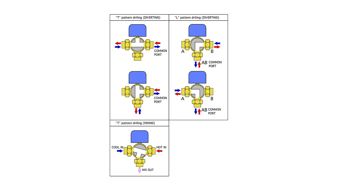 Image courtesy of John Siegenthaler
Valves with “T” pattern drilling can function as either a diverter valve or a mixing valve. The latter is possible because all three ports of the valve can be hydraulically connected when the valve’s shaft is within a certain potion of its travel range. When a “T” pattern valve is equipped with a two-position actuator, it can only function as a diverter valve. However, if equipped with a modulating actuator (0-10 VDC, or 3-wire floating input signal), the “T” pattern valve can blend two inlet streams into a common mixed output stream.
A valve with an “L” pattern ball can only operate as a diverter valve.
The red and blue arrows shown in Figure 2 infer that flow can pass through the diverter valve in either direction.
Installers need to verify which way the valve body is connected to piping. For a “T” pattern valve the common port (e.g., the port that has flow through it in either of the two diverting positions is one of the two side ports. For an “L” pattern valve the common port is always the port opposite the actuator.
Lots of uses
3-way diverting valves have many potential applications. We’ll get into them in part 2.
Looking for a reprint of this article?
From high-res PDFs to custom plaques, order your copy today!


.webp?height=200&t=1783240106&width=200 "An Open & Shut Case (part 1)")
.jpg")