Hydronics Workshop | John Siegenthaler
Injection mixing revisited: part one
Injection mixing remains one of the most adaptable and underutilized methods in hydronic system design.
When the North American “radiant renaissance” took root in the late 1980’s, nearly all of the boilers used in hydronic systems were “conventional” boilers. That designation means that those boilers are not intended to operate at conditions that would cause sustained flue gas condensation. Examples of conventional boilers include those with cast-iron, steel or copper water tube heat exchangers.
For boilers operating on natural gas or propane, flue gas condensation begins at inlet water temperatures below about 130 ºF. Boilers operating on low sulfur #2 fuel oil have lower dewpoint temperatures in the range of 110 ºF.
So, how does one match a boiler that needs these minimum inlet water temperatures with a radiant floor panel that might only need 105 ºF supply water at design load, and even lower water temperatures under partial load? The answer is a mixing assembly that does two things:
- It blends higher temperature water from the conventional boiler with some of the water returning from the radiant panel to create a desired supply water temperature to the radiant panel circuits.
- It keeps the boiler inlet water temperature high enough to prevent sustained flue gas condensation whenever possible.
There are at least six different hardware configurations that can accomplish these requirements. The best known configurations involve 3-way valves operated by either thermostatic actuators or electric motor actuators.
4-way motorized mixing valves can also be used with conventional boilers having low flow resistance (e.g., cast-iron sectional). When properly applied, 4-way motorized mixing valves can eliminate the need for a circulator between the mixing valve and boiler. That’s not possible with any type of 3-way mixing valve.
Nearly all systems using 3-way or 4-way mixing valves require the full flow going to the distribution system to pass through the valve. This requirement often dictates the pipe size of the valve body. For example, a low temperature load requiring 400,000 BTU/hr and operating at a design temperature drop of 20 ºF, would require 40 GPM flow through the mixing valve. That implies a minimum valve port size of 2-inch. A load requirement of 1,000,000 Btu/hr would require a minimum 4-inch valve. These larger mixing valves are available, but they are expensive.
The alternative: Mixing a hot stream of water with a cooler stream to achieve the desired temperature doesn’t have to take place within a valve. It can take place in a tee, a tank, a hydraulic separator or any other “container” where two streams enter and one mixed stream leaves. The name for this concept is injection mixing.
As simple as it sounds, injection mixing has not been as widely understood or applied in hydronic systems compared to the use of mixing valves. That’s unfortunate, because it has lots of potential applications in both legacy and modern hydronic systems.
One of the “classic” applications for injection mixing is in systems where a conventional boiler supplies a low temperature distribution system, such as shown in figure 1.
FIGURE 1
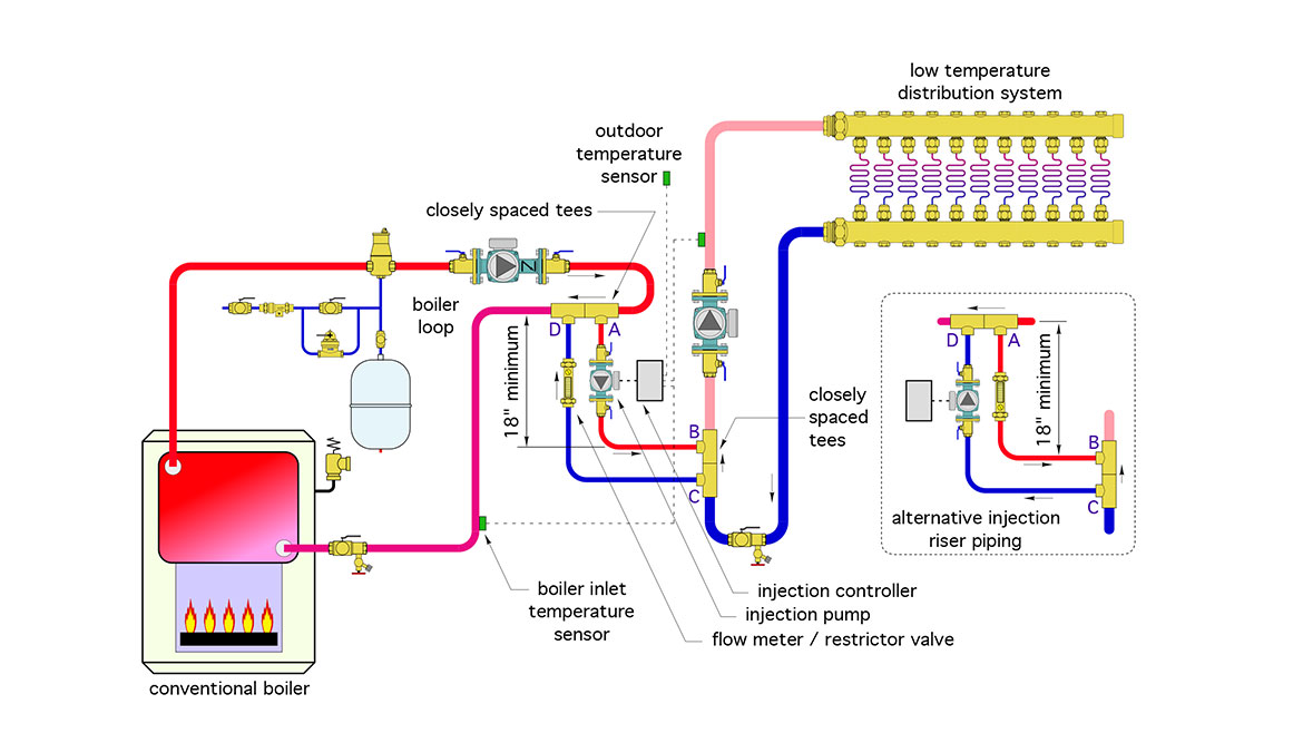
Drawing courtesy of John Siegenthaler
Hot water from the boiler loop flows into the tee at point A. The injection pump creates a flow that moves some of that hot water to point B, where it’s pushed into another tee and mixes with cooler water returning from the heat emitters. An equal flow rate of cool water returns from point C to point D, where it mixes with the remaining hot water flow in the boiler loop. That second mixing point at D increases the water temperature returning to the boiler. If properly controlled, that temperature is high enough to prevent sustained flue gas condensation in the boiler.
The system in figure 1 uses a standard hydronic circulator with a permanent split capacitor (PSC) motor, regulated by a variable speed controller as the injection control device. The faster the circulator runs, the higher the injection flow rate at point B, and the warmer the mixed supply temperature to the heat emitters.
The two pairs of closely-spaced tees at (A,D) and (B, C) provide hydraulic separation between the variable speed injection pump and the other circulators in the system. It’s an important detail, since it allows the injection pump to operate as if it’s in an isolated circuit, separated from any influence from the boiler circulator or distribution circulator(s).
The controller operating the injection pump varies the AC waveform sent to the pump’s motor. This allows speed control all the way from full stop to full speed. The speed at any given moment depends on the settings of the injection controller. It can be configured to provide a setpoint temperature at the supply temperature sensor, or regulate the “target temperature” at that sensor based on outdoor reset control.
The controller also monitors the boiler inlet temperature and, when necessary, slows the injection flow rate to keep that temperature at or above a user setpoint - such as 130 ºF for a gas-fired conventional boiler.
Injection Valves
Although use of a variable speed circulator as the injection control device has been the most common form of injection mixing in North America, it’s not the only option. Modulating 2-way valves can also serve as injection control devices. The valve can be regulated by a non-electric thermostatic actuator, or equipped with an actuator motor operated by an electronic controller
Figure 2 shows how a motorized valve can be used to regulate the rate of hot water flow from a thermal storage tank into a circulating distribution system.
FIGURE 2
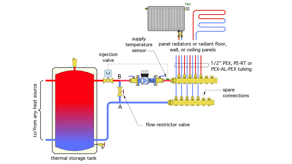
Drawing courtesy of John Siegenthaler
When a valve is used as the injection control device, there must be a way to create sufficient differential pressure across the valve to force the necessary flow through it. In figure 2, that differential pressure is created by the flow restrictor valve. The pressure at point A is higher than the pressure at point B due to the pressure drop through the flow restrictor valve.The higher pressure at A is translated through the tank to the inlet side of the injection valve.
A globe valve is typically used for the flow restrictor valve. However, any type of balancing valve could potentially be used.
The flow restrictor valve must be properly adjusted for optimal performance of the injection valve. The ideal setting is such that the injection valve is fully open while passing the injection flow rate needed for design load conditions. This allow the full range of travel for the injection valve to be “mapped” to the full range of heat input needed by the distribution system.
The injection flow rate needed at design load can be calculated using formula 1.
Formula 1:
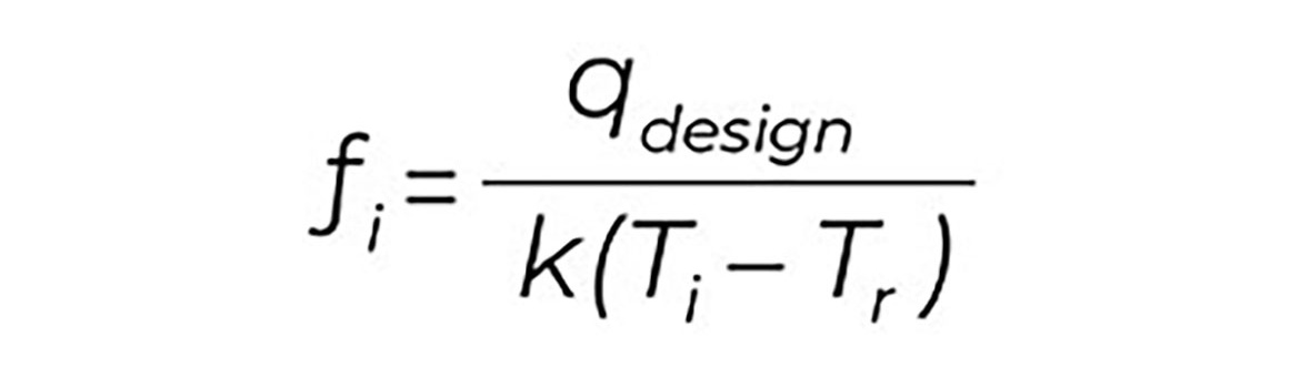
Courtesy of John Siegenthaler
Where:
fi = injection flow rate at design load (gpm)
qdesign = rate of heat transfer at design load (Btu/hr)
Ti = temperature of the “hot” fluid being injected (ºF)
Tr = temperature of “cool” fluid returning from distribution system at design load (ºF)
k = 493 for water, 477 for 30% propylene glycol, 450 for propylene glycol
For example, assume “hot” water from any source is available at 125 ºF, and the water temperature returning from the distribution system, at design load, is 96 ºF. The design load heat output of the distribution system needs to be 50,000 Btu/hr, and the system operates with water. The required injection flow rate is:
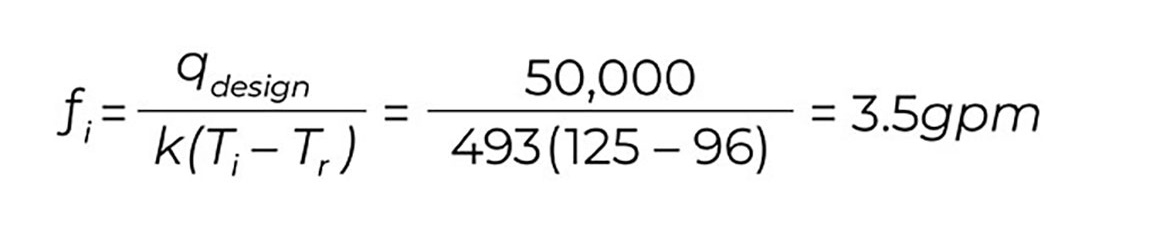
Courtesy of John Siegenthaler
This injection flow rate could be easily handled by a 3/4” injection valve.
A motorized globe valve with an equal percentage plug is well suited as an injection valve. So is a ball valve with a characterized insert. The equal percentage plug in the globe valve, or the characterized insert in a ball valve allows flow to increase slowly as the valve starts to open, and progressively faster as the valve continues toward its fully open position. This allows stable and accurate control, especially under low load conditions.
How does one match a boiler that needs these minimum inlet water temperatures with a radiant floor panel that might only need 105 ºF supply water at design load, and even lower water temperatures under partial load? The answer is a mixing assembly.
A word of caution is in order. When injection mixing is used with a boiler, the hot water temperature remains relatively consistent, with perhaps a swing of 10-15 ºF as the boiler’s burner cycles on and off. However, when injection mixing is used with a thermal storage tank, there can be much wider swings in the “hot” water temperature being injected. The lower the temperature of the injection water, the greater the required injection flow rate to maintain a given rate of heat transfer. Formula 1 can be used to study this effect using different values of (Ti). If the goal is to have design load heat transfer when the thermal storage tank is at its lowest working temperature, be sure the injection mixing valve is sized for the required flow rate.2
There are several more applications where injection mixing can be used. We’ll get into those in next month’s Hydronics Workshop column.
Looking for a reprint of this article?
From high-res PDFs to custom plaques, order your copy today!


