The Glitch & The Fix: Upside down

The Glitch:
Take a look at Figures 1, 2a and 2b. What do they have in common? Can you think of some better ways to accommodate the flexible tubing?
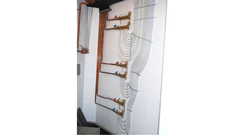 Figure 1
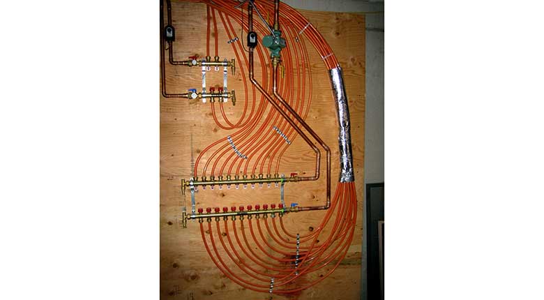 Figure 2a
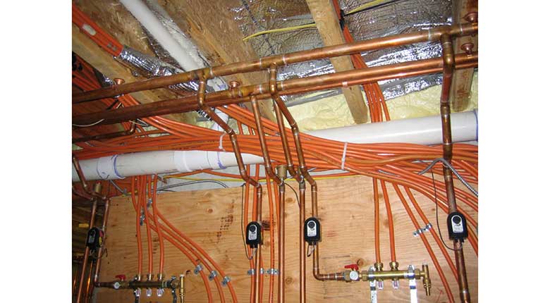 Figure 2b
The Fix
Both installations use much more tubing than necessary. Why route tubing downward only to have it make a U-turn and go upward? Why waste perhaps hundreds of feet of tubing just to get the heated water from a manifold station to several areas well removed from that station?
One way to avoid the problem is to use manifold hardware that points the tubing upward. It might be as simple as flipping the manifold bodies over in their mounting bracket. However, when the individual manifolds have float air vents at their end, those vents must point upward. With some hardware, it might be a matter of loosening a union and rotating the vent assembly. With others, the manifold station needs to be ordered as an “inverted” manifold. Figure 3 shows an example of the latter.
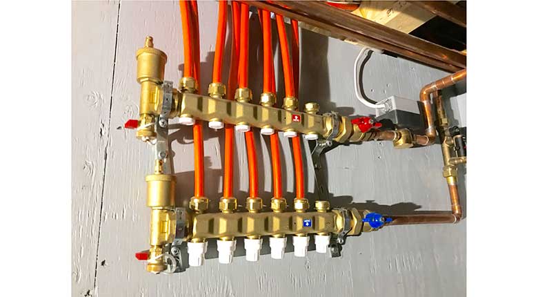 Figure 3
The 1/2” PEX-AL-PEX tubing goes upward, and so does the float air vent at the ends of the supply and return manifolds.
If the manifold will use electric valve actuators be sure that they are rated to be installed on valves that are on the bottom of the manifold. During normal operation, there should be no problem, but if the valve were to develop a leak, it’s likely that water would drain over (or into) the actuator. Some actuators are sealed against water entry, while others are not.
Another fix that will prolong the life of the installer’s angle drill and wood eater bits is to create an extended manifold, an example of which is shown in Figure 4.
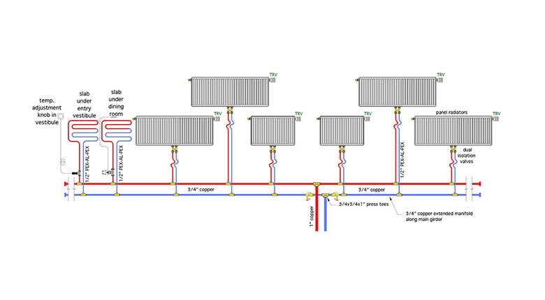 Figure 4 [click image to enlarge]
The idea is simple. Create a linear set of headers that stretch across most of the building areas that will be served by the smaller flexible tubing. They might run down the underside of the floor joists, or along the main floor girder. The flexible tubing (PEX, PEX-AL-PEX, PE-RT) runs from tees on the headers to radiant panel circuits (floors, walls, or ceiling), or to fin-tube baseboard, panel radiators, fan-coils, towel warmers or any combination of these emitters. Just be sure that all heat emitters are sized for the same supply water temperature.
The headers could be made with any kind of tubing that installs straight and can be fitted with reducing tees. Copper would be common in residential systems, but PEX, PEX-AL-PEX, or PP-R tubing could also be used. Figure 5 shows an example of the latter. Saddle fusion tees were used at each location where a 3/4” PEX tube connects to the headers.
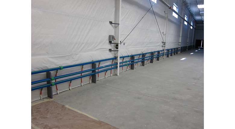 Figure 5a
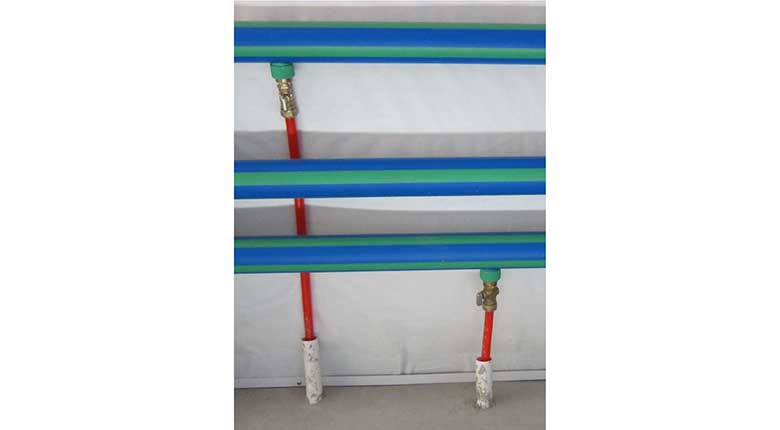 Figure 5b
Even in a typical residential project extended manifolds can often eliminate several hundred feet of small flexible pipe, several dozen holes through framing and the time required to pull the tubing through all those holes.
Looking for a reprint of this article?
From high-res PDFs to custom plaques, order your copy today!


.jpg")
