The Glitch & The Fix: Busy backup


The Glitch:
A heating designer is asked to create a three zone radiant floor heating system using a 5-ton (60,000 Btu/h) geothermal heat pump as the primary heat source, and a mod/con boiler as the auxiliary heat source. Because of the symmetry of the building, each zone will have a six circuit manifold station with nearly identical circuit lengths. All the floor heating circuits are underfloor tubing with aluminum plates stapled tightly to the underside of the sulfuring and well insulated.
The designer sets up a primary secondary system where each heat source connects to the primary loop using a pair of closely spaced tees, as shown in Figure 1.
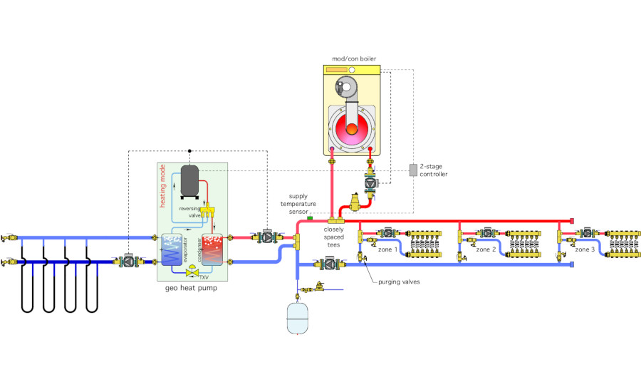
Each manifold station is also supplied from a pair of closely spaced tees installed in parallel “crossovers” of the primary loop. This keeps the supply water temperature to each manifold station approximately equal. The system has a seven identical 1/25 HP circulators.
The two heat sources are controlled by a 2-stage setpoint controller. When there’s a demand for heat from any of the zones that controller looks at the temperature at the supply sensor, and uses the following logic:
Stage 1:
If Ts ≤ 115ºF then heat pump = ON
If Ts ≥ 117ºF the heat pump = OFF
Stage 2:
If Ts ≤ 112ºF then boiler = ON
If Ts ≥ 125ºF the boiler = OFF
When put into operation the heat pump short cycles. The boiler runs much longer than the heat pump.
Look over the system closely. Can you spot several details that are either incorrect or missing? Can you propose an alternative design that would accomplish the same goals using less hardware?
The Fix:
The system in Figure 1 is peppered with errors and omissions, including:
- A 1/25 HP circulator might be adequate for a zone, but it’s not going to have sufficient head and flow to serve a 5-ton geothermal heat pump;
- There’s no air separator or expansion tank in the earth loop;
- All earth loop circuits must be filled and purged in parallel. While possible, this requires a much more powerful purging pump, compared to situations where each loop can be filled and purged individually;
- Both circulators on the heat pump are “pulling” flow through their respective heat exchangers. These heat exchangers typically have high pressure drops. This combination could lead to cavitation in the circulators. It always better to “push” flow into high resistance components. Same point for the boiler circulator;
- The controller on/off settings for stage 1 are much too close, especially for a low thermal mass radiant panel. This is the underlying cause of the short cycling;
- The off-setting for stage 2 is several degrees higher than stage 1, causing the boiler to remain on after stage 1 has been “satisfied,” and thus turns off;
- The expansion tank is poor placed relative to the circulators, this will cause drop in system pressure when the primary loop circulator is on;
- Two of the purging valves are upside down;
- There’s no pressure relief valve in the system;
- There will be some flow imbalance between the manifold stations due to the use of direct return piping. The zone 1 crossover will get more flow than that of zone 2. The zone 2 crossover will get more flow than zone 3;
- The supply temperature sensor should be downstream of both heat sources. As shown in Figure 1 it senses heat input from the heat pump, but not (directly) from the boiler. Once the boiler is turned on it will remain on until the return temperature from the crossovers reaches 125° F, which is significantly higher than necessary;
- The air separator should be available to both heat sources, not just the boiler;
- The position of the backflow preventer and pressure reducing valve on the make-up water system is reversed; and
- There is no way to isolate either heat source from the remainder of the system is necessary for service.
One way to eliminate these issues is shown in Figure 2.
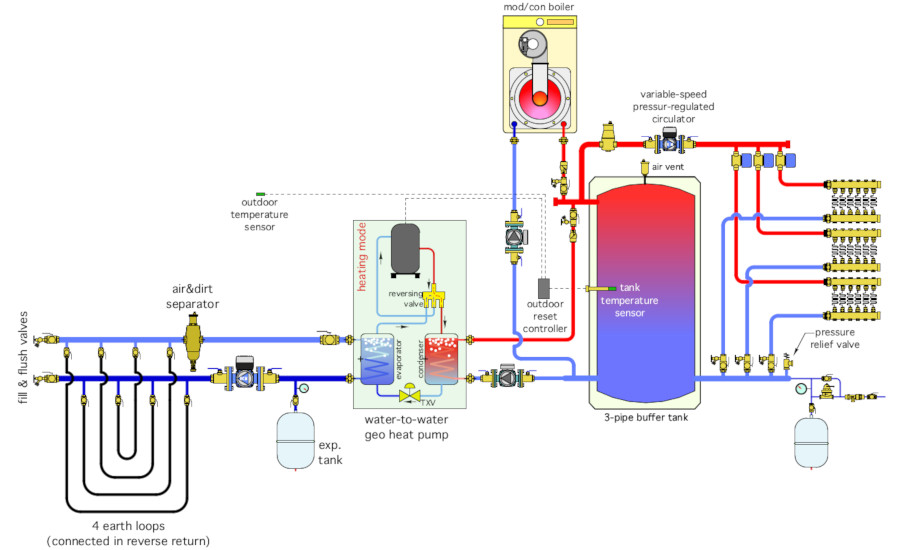
Both heat sources can operate individually or in parallel supplying heat to a buffer tank. The mass of the buffer tank stabilized the system against short cycling.
The temperature of the buffer tank is now controlled by a 2-stage outdoor reset controller rather than a setpoint controller. The heat pump is the fixed lead heat source, and the boiler the backup. As the outdoor temperature increases the temperature of the buffer tank is reduced, which increases the COP of the heat pump and the efficiency of the boiler.
The distribution system is zoned with valves and supplied by a pressure-regulated variable speed circulator. This reduces circulator count and greatly reduces the electrical energy required to operate the system.
Each heat source can be isolated from the remainder of the system if necessary for service. Check valves are used to prevent flow reversal or heat migration through either heat source when it is off. A combination air/dirt separator and expansion tank have been added to the earth loop system.
Each earth loop can be isolated by ball valves, allow for faster filling and flushing. A pressure relief valve and properly configured make-up water assembly have been added to the system.
The earth loop circulator is pumping away from the expansion tank location, and thus increasing pressure in the earth loop circuits and heat pump evaporator when operating.
Download The Glitch and Fix: December 2020 in pdf form.
Looking for a reprint of this article?
From high-res PDFs to custom plaques, order your copy today!


.jpg")
