The Glitch & The Fix: Zone 3 failure
Can you figure out why this boiler circulator failed?
The Glitch:
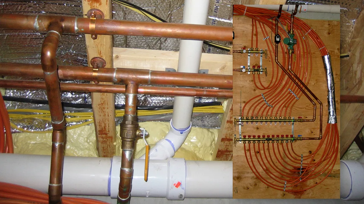
Take a look at the piping in figure1.
FIGURE 1
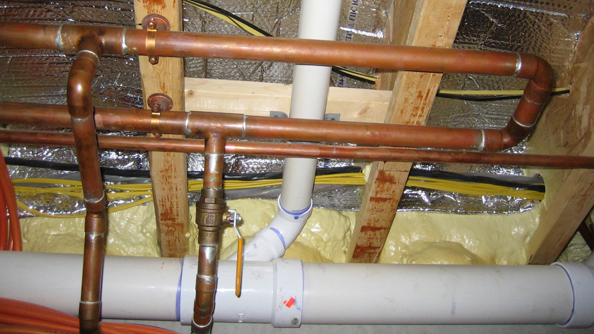
Image courtesy of John Siegenthaler
The horizontal piping is the end of a “boiler loop” assembled with 1” copper tubing and fastened to the underside of floor framing.
Figure 2 shows the 3/4” copper tubing that tees into that boiler loop going down to a manifold station. The pipe on the right passes through a ball valve, then down through a circulator. The pipe on the left passes up through a zone valve.
FIGURE 2
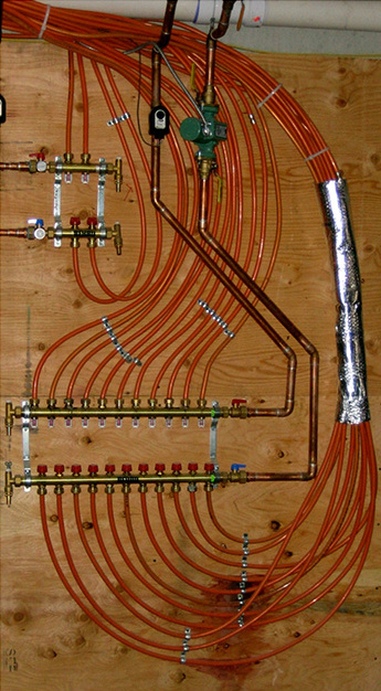
Image courtesy of John Siegenthaler
Figure 3 is a partial schematic of the overall system.
FIGURE 3
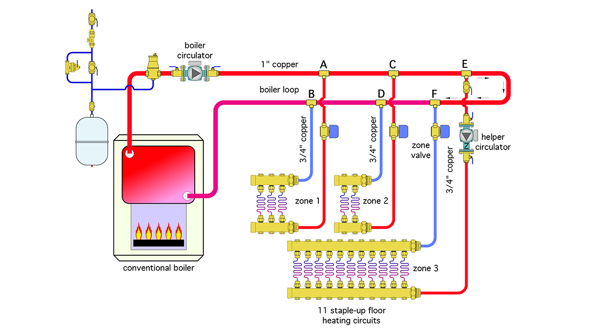
Drawing courtesy of John Siegenthaler
The “intent” for this system was three independently controlled zones. The boiler circulator was set up to run when any zone valve opens.
Zones 1 and 2 provided adequate comfort, but zone 3 did not. In an attempt to remedy the situation, the installer returned and added a “helper circulator” in zone 3 that operates along with the zone valve.
Can you speculate why heat delivery in zone 3 was insufficient prior to the helper pump? Can you come up with a better way to pipe this system? Try to look past the waste of a couple hundred feet of PEX-AL-PEX tubing leading from the manifold stations up to the floor panels in figure 2 as you think about how to rework the system.
What’s wrong
This is another one of those “undefined” piping layouts that attempts to meld the concepts of a primary loop and a header system.
The only differential pressure that drives flow through zone 1 is the pressure drop between points A and B as water flows around the boiler loop. Likewise, the only differential pressure that drives flow through zone 2 is that caused by pressure drop between points C and D as water flows around the boiler loop. Apparently, since zone 1 only serves three floor circuits, and zone 2 only serves 3 floor circuits, the differential pressure developed is sufficient to keep the rate of heat delivery above the “callback threshold.”
Too bad that’s not what’s happening in zone 3. The only differential pressure pushing flow through zone 3 (prior to adding the helper circulator) was the pressure drop between points E and F due to flow around the boiler loop.
Since zone 3 serves 11 circuits, it requires substantially higher flow than zones 1 and 2. I often suggest a nominal flow of 1 GPM per 1/2” floor heating circuit. If that were the goal, zone 3 would need to operate at around 11 GPM. That would mean the 3/4” copper tubing serving the zone 3 manifold station would operate at a flow velocity of about 6.8 feet per second. That’s high enough to create flow noise and eventual erosion corrosion.
The helper circulator does “help,” but there’s another potential problem. If the flow through zone 3 with the helper circulator is greater than the flow in the boiler loop, some of the flow returning from the zone 3 manifold will go backwards from point F to point E in the boiler loop. This will cause mixing at point E that reduces the supply temperature to zone 3.
The fix
The hydraulic solution to this situation is relatively straight forward:
- Cut and cap the end of the boiler loop, convert the system to headers.
- Upsize the piping leading to the zone 3 manifold to 1” copper.
- Install flow indicating balancing valves in each of the zones.
- Install a purging hose bib under each balancing valve.
- Install a variable-speed pressure-regulated circulator in place of the boiler circulator.
Figure 4 shows these modifications.
FIGURE 4
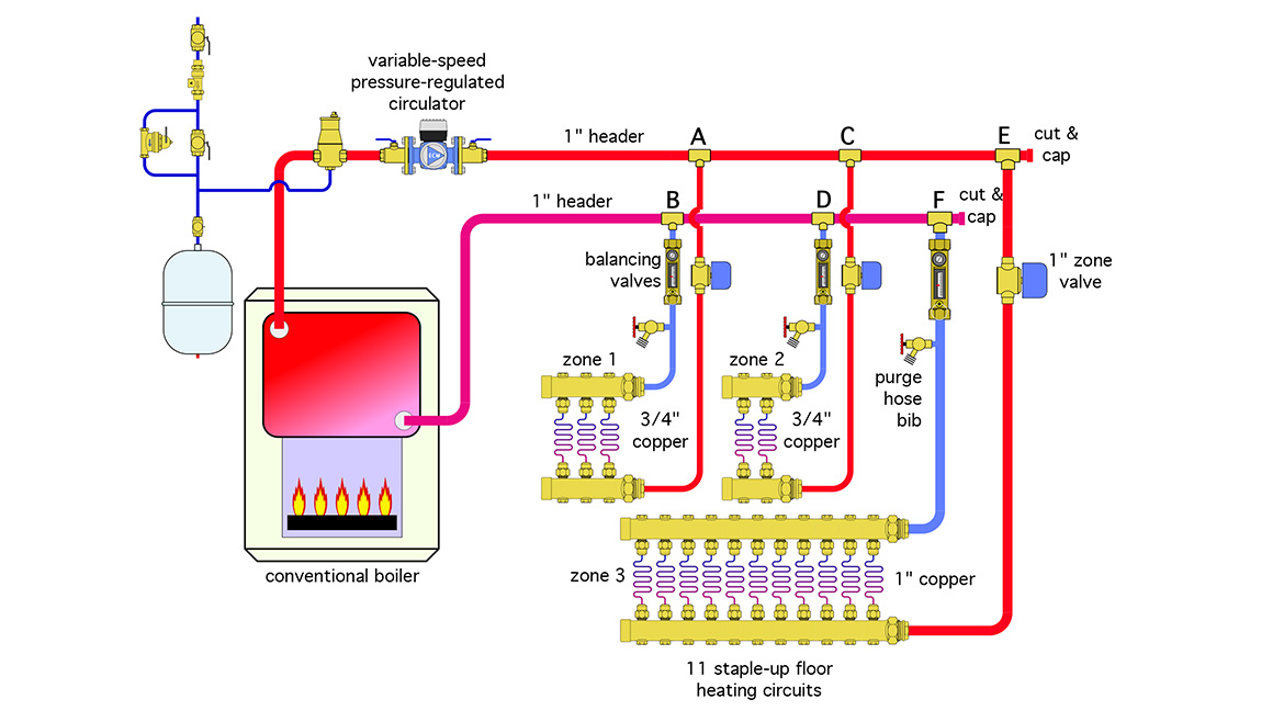
Drawing courtesy of John Siegenthaler
Converting the 1” boiler loop to 1” headers is a compromise. The 1” headers are still a bit small if the goal is to get 11 GPM out to zone 3, especially when zones 1 and 2 are also operating. Ideally, I would suggest 1.5” headers. The larger headers would reduce flow rate variations as individual zones operate in different on/off combinations. Still, if there’s limited times when all three zones would operate simultaneously, keeping the existing 1” pipe is arguably a reasonable compromise.
Zone 3 will dominate when it comes to selecting and configuring the new variable-speed pressure-regulated circulator. It should be sized for the total flow rate with all zones operating, and the head loss of the supply and return headers added to the head loss through all components in zone 3, assuming a nominal 11 GPM to the zone 3 manifold station. The CV of the new 1” zone valve should be as high a possible to minimize this head loss.
Finally, when you need to route tubing from a manifold station up to floor panels please look into “inverted” manifolds that mount to a wall and have branch piping connections pointing up along with their float vent. Another option is mounting manifold stations that don’t have float vents horizontally, between, or just below the floor framing as shown in figure 5. You’ll save a lot of tubing and reduce heat loss compared to the “artistry” shown in figure 2.
FIGURE 5
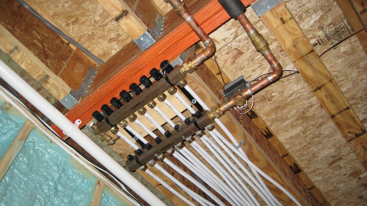
Image courtesy of John Siegenthaler
Looking for a reprint of this article?
From high-res PDFs to custom plaques, order your copy today!


.jpg")
