The Glitch & The Fix: October 2025
Hindsight - From complex loops to clean headers: simplifying for reliability

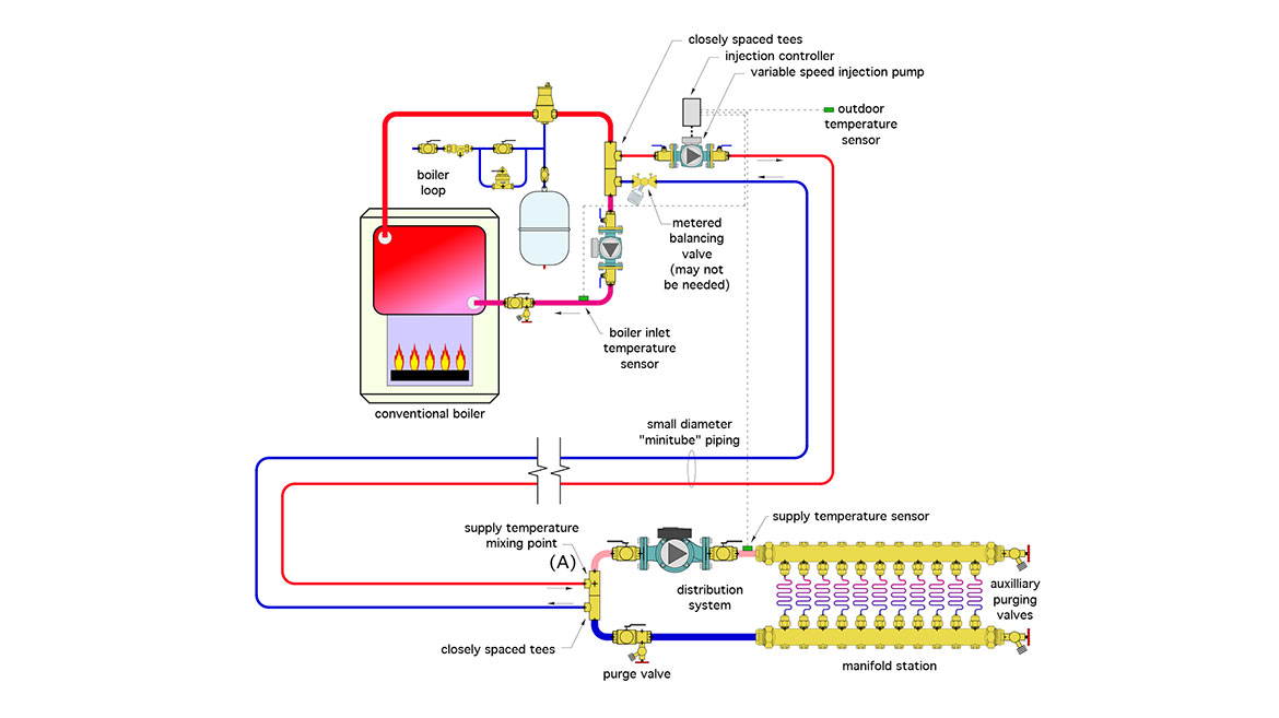
About 25 years ago, I began using a design technique that sends high temperature water to a remote manifold station serving low temperature floor heating circuits. Upon arrival at the manifold, that high temperature water gets mixed with water returning from the floor heating circuits to create a suitable supply water temperature for the embedded circuits. The rate of hot water flow to the manifold station was regulated by a variable speed "injection" pump. The concept is shown in figure 1.
FIGURE 1
Drawing courtesy of John Siegenthaler
The advantage of this approach was a significant reduction in the pipe size needed to transport heat to the manifold station. This is possible because of the high temperature difference between the hot water going to the manifold station (say 180 ºF), and the water returning from the manifold station (say 90ºF). Since that ∆T is about 4 times greater than the typical ∆T of floor heating circuits ( 15 ºF), the flow rate needed for a given rate of heat transport is only about 1/4 of what would be required with the 15 ºF ∆T. That lower flow rate allows 3/4" PEX-AL-PEX tubing to replace 1.5" copper. In large buildings where manifold stations can be located 100+ feet from the mechanical room the savings in distribution piping cost can be thousands of dollars.
I called this approach a "minitube" system.
Multi-zone minitube
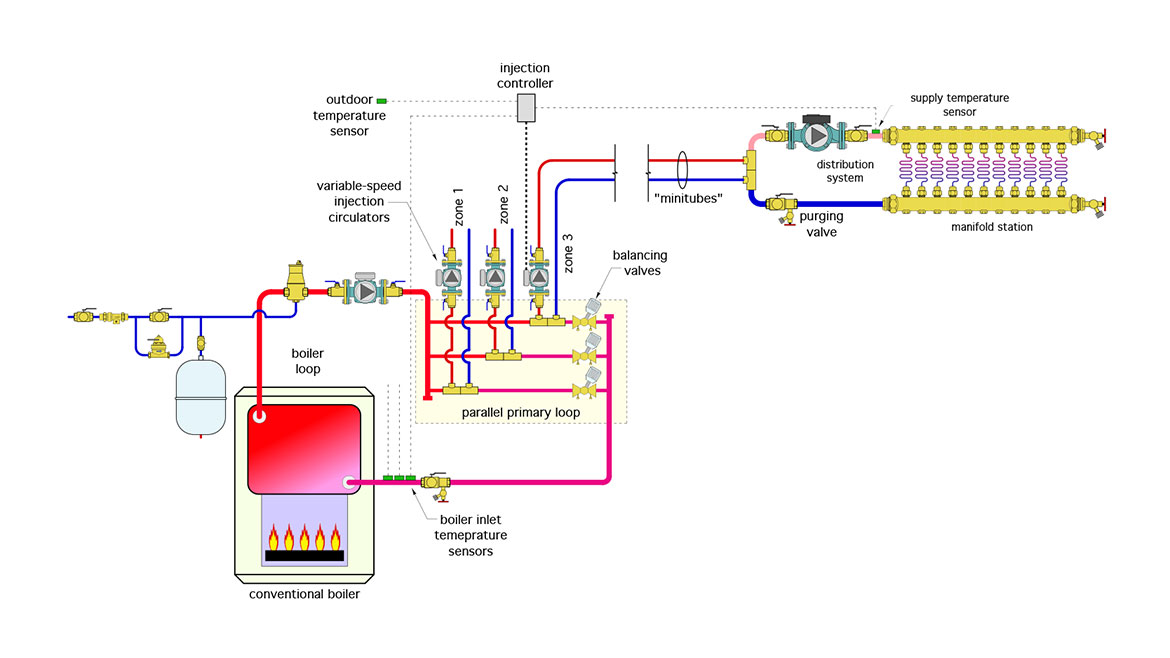
The minitube technique can be used on systems with multiple manifold stations. Doing so requires the same hot water temperature to be available to each manifold. It also requires hydraulic separation of the multiple variable-speed injection circulators.
My original approach to these requirements was heavily influenced by the popularity of primary / secondary piping at the time. I used a parallel primary loop, as shown in figure 2.
FIGURE 2
Drawing courtesy of John Siegenthaler
The parallel primary loop provides the same water temperature to each set of closely-spaced tees. However, it involves quite a bit of piping and fittings, as well as a balancing valve on each crossover.
The concept shown in figure 2 was used for a floor heating system in a highway garage. The installation work was awarded to the lowest bidder. The system worked, but the "craftsmanship" applied during the installation was, well, let’s just say marginal. This became more evident over time. Multiple joints eventually revealed that they were not properly sealed. The slowly oozing antifreeze solution created an ugly patina on several portions of the copper tubing (see figure 3).
FIGURE 3
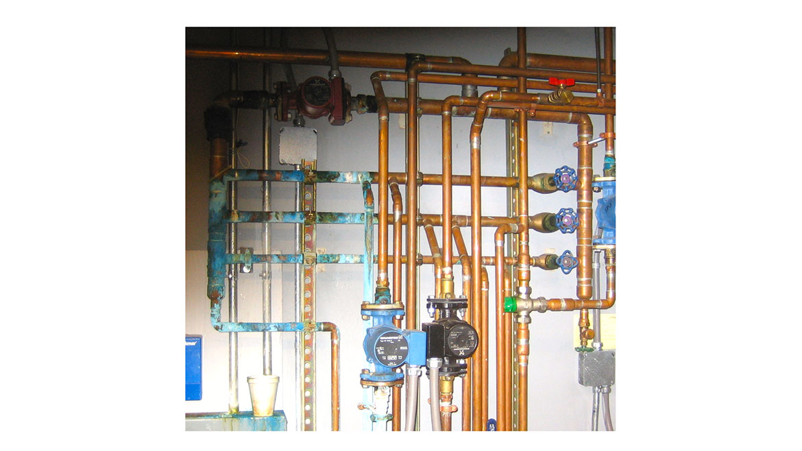
Image courtesy of John Siegenthaler
Although the system continued to work, and the building was properly heated, the client eventually decided to replace portions of the heavily corroded piping. That’s where hydraulic separation - a concept that I was just beginning to appreciate - was used to simplify the replacement piping.
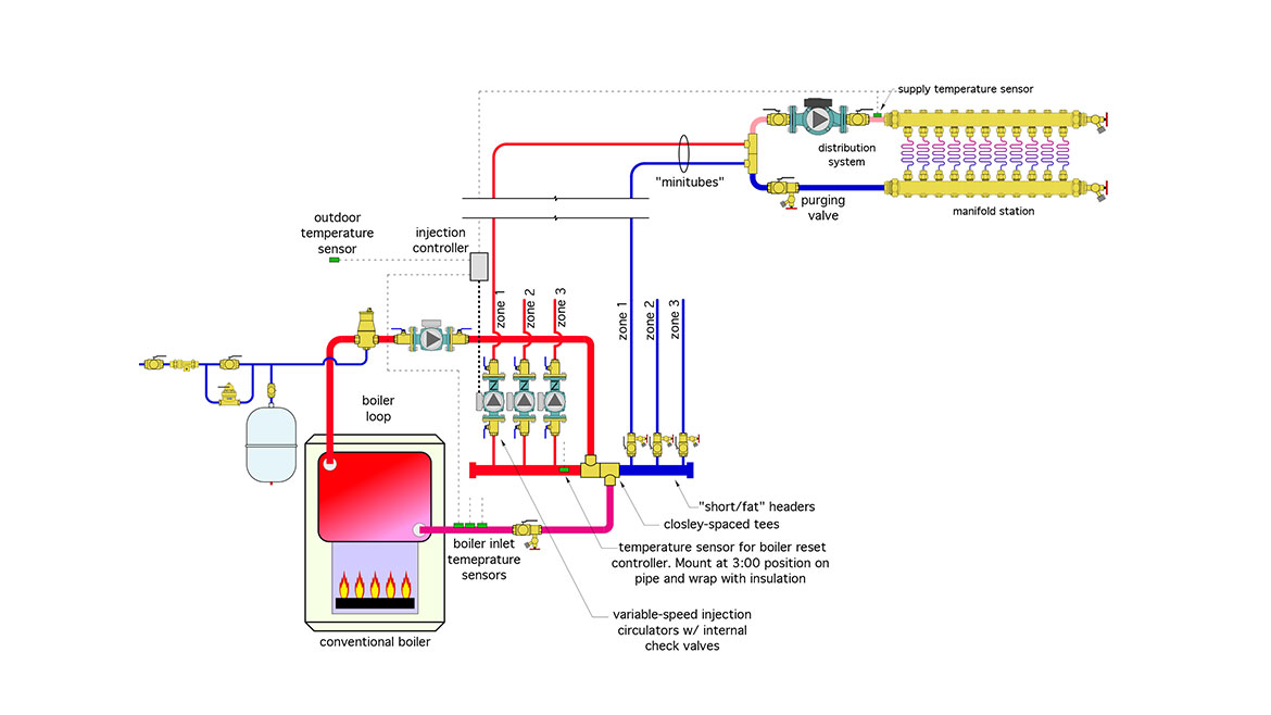
The parallel primary loop seen in figures 2 and 3 was replaced by a simple "short/fat" header as shown in figure 4.
FIGURE 4
Drawing courtesy of John Siegenthaler
To achieve hydraulic separation the piping that’s "in common" with all the circuits needs to have minimal head loss.For the three variable speed injection circulators in figure 4, that common piping is a minimal length of larger piping (e.g., the "short/fat" headers). In this system, which has a capacity of 400,000 Btu/hr, those "short/fat" headers are 2" copper, and the minitube circuits are 3/4" copper transitioning to 3/4" PEX-AL-PEX for most of the run out to the manifold stations. The boiler circulator is separated from the injection circulators by the closely spaced tees between the supply and return headers serving the minitube circuits.
The system worked, but the "craftsmanship" applied during the installation was, well, let’s just say marginal. This became more evident over time.
Each injection circulator is independently controlled based on the demand of their associated zone. Each injection controller needs a boiler inlet temperature sensor to ensure that the boiler is not operated at conditions that would cause sustained flue gas condensation.
Figure 5 shows the partially completed reworked piping. It’s definitely "cleaned up" and simplified compared to the piping in figure 3. The revision removed the parallel primary loop but left as much of the original piping as possible in place.
FIGURE 5
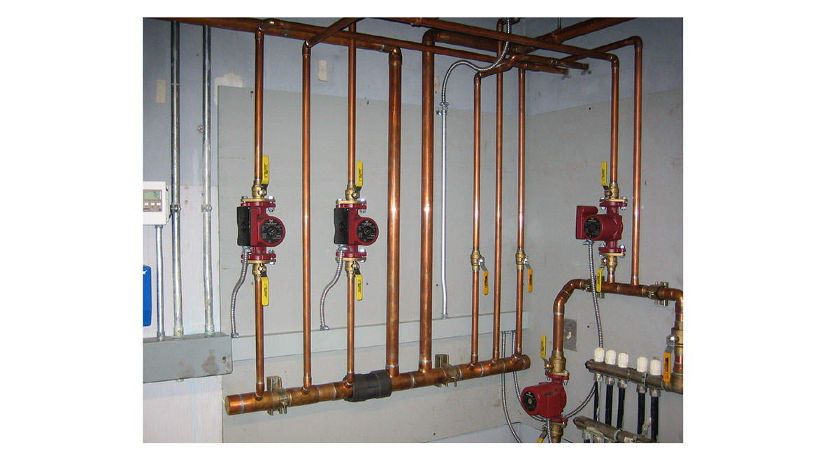
Drawing courtesy of John Siegenthaler
Hindsight is always 20/20. Although the parallel primary loop approach worked, the opportunity to improve a marginal installation, combined with a better understanding of the requirements for hydraulic separation, led to much simpler piping that provided the same performance. It was a lesson applied to many subsequent designs.
Looking for a reprint of this article?
From high-res PDFs to custom plaques, order your copy today!