Renewable Heating Design | John Siegenthaler
Aesthetic, efficient and resilient: hydronics outclass multi-splits in key areas
Zoning has always been a premier benefit of hydronic heating and cooling systems. There are many zoning configurations capable of delivering heat (or cooling effect) when and where it’s needed in a building, with minimal effect on the temperature in other parts of the building. Some methods use circulators to create flow in each zone; others use either motorized or thermostatic valves to regulate flow. In most residential systems, a single heating or cooling source, such as a boiler or heat pump, provides the thermal energy to a distribution system that’s entirely inside the building being heated or cooled.
While the text in italics in that last sentence might seem obvious to professionals who work with hydronic systems, it’s a benefit that often gets little if any attention when a hydronic system is compared to other heating and cooling options.
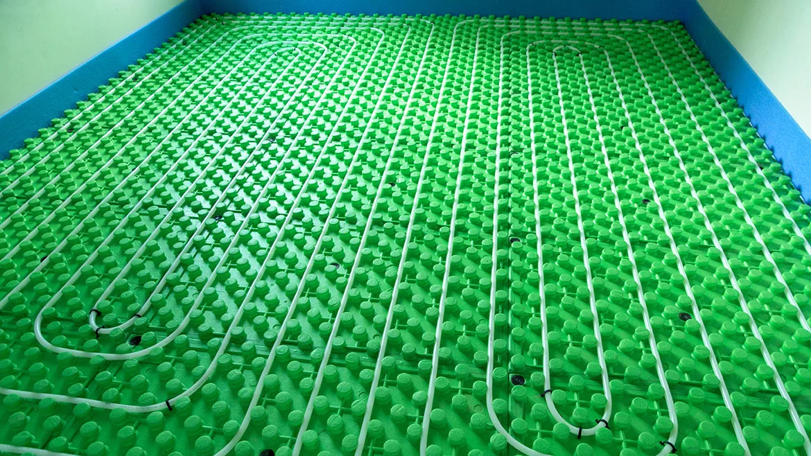
Tentacles: Mini-split “ductless” heat pumps are currently one of the most heavily marketed approaches to multi-zone heating and cooling. Drive around almost any neighborhood and you’re sure to see outdoor condenser units connected to two or more plastic raceways running along the exterior of houses or light commercial buildings, such as shown in figure 1.
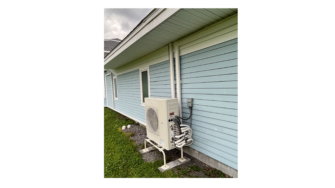
Image courtesy of John Siegenthaler
I get it. In retrofit situations, it’s easier to route tubing raceways along the outside of the building and then punch through the wall near the interior fan-coil. But, “easy” isn’t always best, especially over the long term. Aside from compromised aesthetics, if these raceways are run along siding that needs to be periodically stained or painted the situation comes down to either temporarily moving the raceways and lines sets, or simply not maintaining the surface finish behind them. Over time, the inability to maintain that surface finish, combined with moisture trapped behind the raceways can lead to mold, rot, insect nests, and discoloration. After a typical 15-18 year service life, those raceways may have to be removed, and any underlying damage repaired.
Speaking of aesthetics, take a close look at the 5-zone mini-split condenser unit in figure 2.
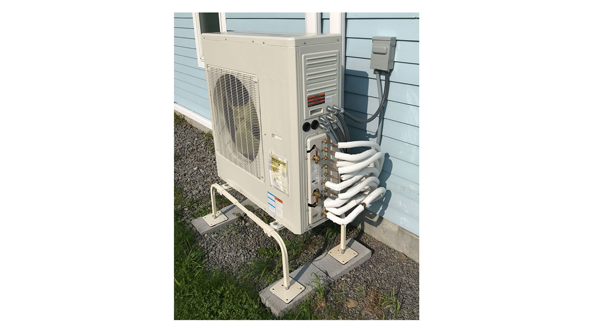
Image courtesy of John Siegenthaler
Kudos to the installer who connected this unit. They did a nice job of wrapping 10 refrigerant tubes and 6 liquid tight electrical conduits behind the condenser. Still, it’s worth considering that just about anyone with a crescent wrench could easily vandalize this unit, and with a little more effort and a $25 tool, make off with a lot of copper tubing.
The mini-split condenser unit in figure 3 has 8 copper refrigerant tubes and 5 liquid tight electrical conduits attached. This photo was taken after carefully digging out the condenser unit and line sets following a major winter storm that completely buried them.
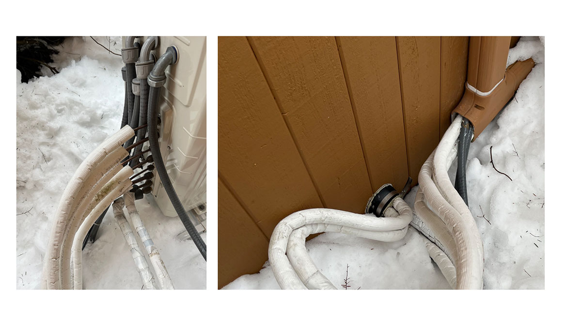
Image courtesy of John Siegenthaler
The heavy snow definitely stressed the line sets and the raceways. You can see that the horizontal raceway was pulled downward at the tee due to the weight of the snow. If these line sets and the electrical harnesses had not been carefully “excised,” that stress may have led to kinked copper tubing, refrigerant leaks, broken electrical connections and broken raceways.
Higher and Drier: The air-to-water heat pump shown in figure 4 has two tubes carrying an antifreeze solution to and from the unit.
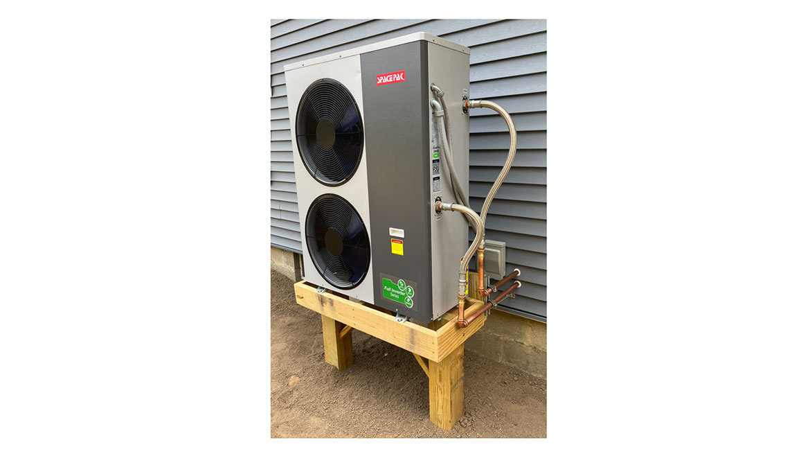
Image courtesy of John Siegenthaler
The unit also has a liquid tight conduit for power, and another small liquid tight conduit for low voltage wiring. The heat pump as well as the tubing and conduit are elevated well above the ground to avoid being covered with snow. The copper tubing is well supported. All the piping and flexible pressured-rated hoses were eventually insulated to minimize heat loss and prevent condensation formation during cooling operation.
Compare: Let’s assume you have a potential client who wants a heat pump system. They expect it to do heating and cooling. They also want a mechanical ventilation system with heat recovery, and, like most Americans, they expect an ample supply of domestic hot water.
Figure 5 shows one way to meet these needs. It’s based on a 5-head mini-split system for heating and cooling. A heat recovery ventilator is included along with a ducting system to deliver fresh air to several locations in the house. Domestic water heating is provided by a heat pump water heater.
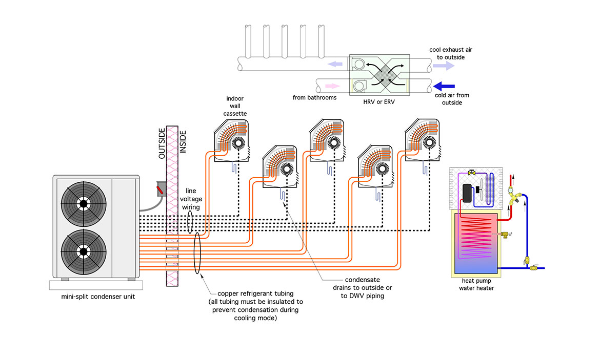
Image courtesy of John Siegenthaler
Five separate copper line sets (10 tubes total) are required between the outdoor unit and the wall cassettes. All that copper tubing has to be insulated to prevent condensation formation during cooling and to reduce heat loss, especially from the outdoor piping.
Five-line voltage wiring runs, each with 4 insulated conductors, are also required between the outdoor “mother ship” and the indoor units.
Each wall cassette also requires a condensate drain that needs to be routed outside or to a DWV stack when allowed by code.
From the standpoint of maintenance, the filter in each interior wall cassette must be periodically cleaned. In many cases it’s also necessary to clean the coil and surrounding surfaces within each indoor unit to remove mold. Check out We Clean Heat Pumps for more information on how annual cleanings on mini-split systems are done. Be sure to watch this youtube video if you don’t think that mini-split cassettes need cleaning.
The “net” COP for the heat pump water heater will be lower than its rating because that rating doesn’t assume that the low temperature heat absorbed by the heat pump is coming from another heat pump, (e.g., the mini-split system). See my column for more details on calculating the “net” COP for heat pump water heater applied in this manner.
Hydronic Alternatives: Figure 6 shows how the needs of the client could be met using a system based on an air-to-water heat pump.
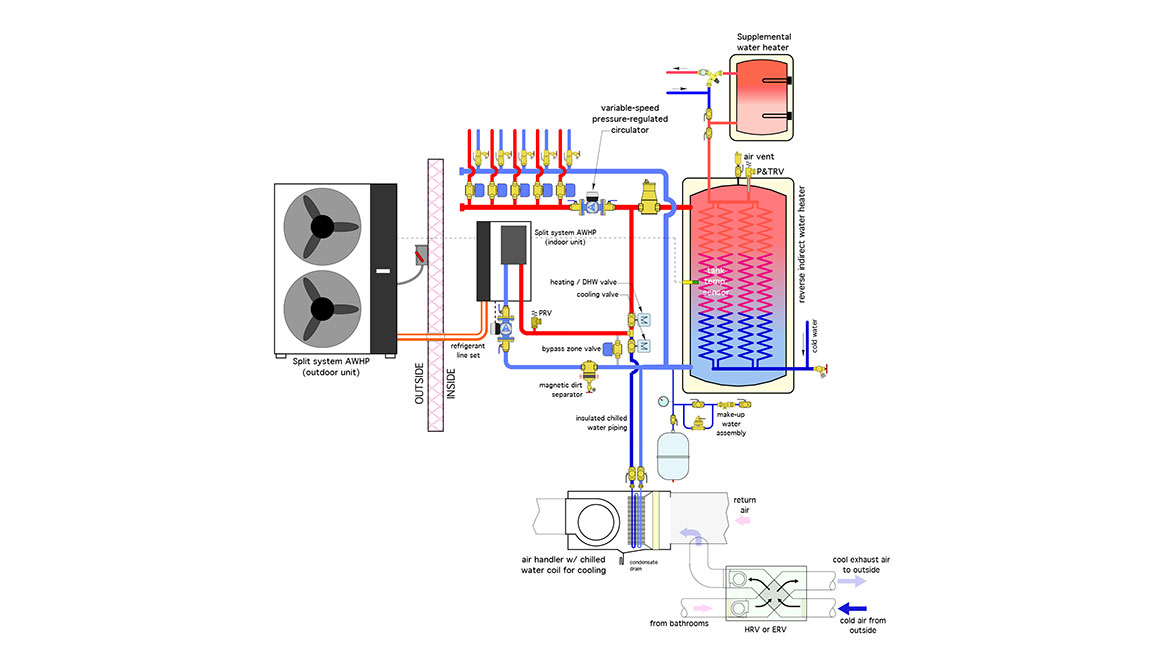
Image courtesy of John Siegenthaler
The air-to-water heat pump is a “DX split” configuration, which uses a single refrigerant line set between the outdoor and indoor units. This allows the remainder of the hydronic system to operate with water (e.g., no requirement for antifreeze).
This system uses a reverse indirect tank as both a buffer tank and domestic water preheat device. The heat pump maintains the temperature in this tank based on either a temperature setpoint with differential, or outdoor reset control. The latter improves the seasonal COP of the heat pump, since the tank is only kept warm enough to supply the building’s heating load based on the current outdoor temperature. However, the “downside” to outdoor reset control in this application is reduced domestic water preheating as outdoor temperature rises. This requires a supplemental domestic water heater such as an electric tank unit or on-demand electric water is down for service.
Most air-to-water heat pumps currently for sale in North America are operating with R-32 or R-454b. Maintaining the tank temperature in the range of 110-115 ºF is well within their operating envelope, and should yield reasonably good COPs. Doing so also shifts most to the DHW temperature rise to the heat pump rather than the resistance elements in the supplemental domestic water heater. This improves the net COP for water heating in comparison to that from a heat pump water heater.
Cooling is provided by a single chilled water air hander connected to a ducted delivery system. That same ducting delivers fresh air from the HRV. The air delivery rate changes based on operating mode. In cooling mode, the air flow rate is 350-400 CFM / ton. In ventilation only mode, the total air flow rate is 120-150 CFM.
The combination of two motorized ball valves, and the bypass zone valve provides two important functions:
- When the heat pump starts both motorized ball valves are closed, and the bypass zone valve is open. This allows the heat pump to start its circulator, verify its flow rate, start its compressor and heat the water to a suitable temperature before sending it to the load or the buffer tank. Doing so also helps maintain beneficial temperature stratification within the buffer tank.
- During mode switching, these valves and their associated control logic prevent residual hot water in the piping from being forced through the cooling coil in the air handler. It also prevents residual chilled water in the piping from being pushed into the reverse indirect water heater.
The system uses a variable-speed pressure-regulated circulator to create flow through any of the five zone circuits. Circulator speed automatically adjusts to maintain a constant differential pressure as the zone valves open and close.
Even Simpler: Figure 7 shows a modification of the system from figure 5. It uses a “homerun” distribution system to supply five panel radiators, each equipped with a thermostatic radiant valve, and thus providing five independently controlled heating zones.
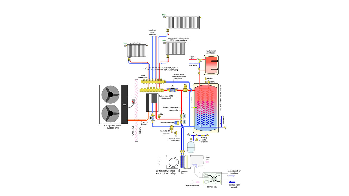
Image courtesy of John Siegenthaler
Each panel radiator is supplied by two 1/2” PEX tubes. In a typical installation, these tubes are all routed within conditioned space, and they don’t carry chilled water. As such, they don’t necessarily have to be insulated. Compare the installed cost of two uninsulated 1/2” PEX tubes for each radiator to that of two insulated copper tubes for each cassette in a 5-zone mini-split system.
The single variable speed circulator operates 24/7 during the heating season, automatically changing speed as the thermostatic radiator valves open, close, or modulate flow. The low power circulators required for this type of system can often operate on 20-30 cents worth of electricity over a 24 hour period.
The other details are essentially the same as in the system of figure 5.
Think About It: Here’s a summary of these alternate ways to provide five zones of heating, cooling, domestic hot water, and heat recovery ventilation.
- There are far more piping and electrical penetrations through exterior walls needed for a 5-zone mini-split system compared to those required for the air-to-water heat pump system.
- All the refrigerant tubing in a mini-split system has to be insulated. In most hydronic systems, only the piping and components conveying chilled water requires insulation to prevent condensation.
- The exposed refrigerant tubing and electrical conduits adjacent to the condenser unit are subject to stress from heavy snow accumulation. The exterior refrigerant connection is also easily vandalized - especially when the price for scrap copper is high…
- In many retrofit applications, the line sets used for a mutli-zone mini-split system are usually run through raceways fastened to the outside of the building. This increases material and labor costs, compromises exterior aesthetics, and may create problems with the siding.
- Exterior pipe routing significantly increases heat loss compared to piping routed within the building’s thermal envelope. For example, a 1/2-inch copper tube covered with 1/2-inch elastomeric foam insulation, and transporting fluid at 150 ºF with a surrounding air temperature of 20 ºF, losses about 16 Btu/hr/ft. A 3/8” copper tube with the same insulation and operating at 110 ºF fluid temperature the loss is about 9 Btu/hr/ft. If the 5 zone mini-split system needed 100 feet of the 1/2” tube (for refrigerant vapor), and 100 feet of the 3/8” tube (for refrigerant liquid), and this tube was all outside the building’s thermal envelope, the total heat loss would be around 2,500 Btu/hr. That’s enough heat to maintain a 250 square foot bedroom in a well insulated house (10 Btu/hr/ft2) under design load conditions. If the hydronic system shown in figure 7 was used in a retrofit situation, the 1/2” PEX tubing to and from the radiators would typically be routed through framing cavities within the building’s thermal envelope. Heat lost from that tubing would contribute to meeting the building’s heating load.
- The mini-split approach requires completely separate systems for DHW and heat recovery ventilation.
- The heat pump water heater essentially “ scarfs” heat produced by the mini-split system, resulting in lower “net” COPs for the water heating load. The hydronic system uses the air-to-water for most of the domestic water heating load resulting in higher “net” COPs for the water heating load.
- A dedicated ducting system is required to install an HRV or ERV in combination with the mini-split system. With the hydronic approach the ventilation air is delivered through the same ducting used for cooling.
- In a mini-split system, each interior wall unit requires filter servicing and periodic cleaning to remove mold and bacteria from the coil and surrounding surfaces. With the hydronic system, a single chilled water air handler provides cooling. Only one point of service is required (e.g., for filter replacement and coil cleaning), and that service point is typically not located in finished/occupied space.
- The volatility of refrigerant regulations may affect the long-term usefulness of the piping in a mini-split system. To some extent, these regulations might also affect the refrigerant piping associated with an air-to-water heat pump. However, with the hydronic system everything other than the heat pump operates with water. H2O is the same yesterday, today and tomorrow.
- Given the number of flare joints involved in a multi-zone mini-split system, there is more potential for refrigerant leakage. There is also more refrigerant volume that may have to be replaced if a leak occurs.
- When a component such as a drip pan, blower or controls within an indoor cassette of a mini-split system fails, it’s possible that the entire cassette will have to be replaced. This requires refrigerant reclaim, disconnection of refrigerant tubing, condensate drain and electrical wiring. These all have to be reconnected to a replacement cassette, the system needs to be pressure tested, evacuated and a new refrigerant charge weighed in. It’s all possible, but it’s also likely to take several hours of tech time and generate a commensurate service invoice.
- The heat needed to defrost the outdoor refrigerant coil in the mini-split system comes directly from conditioned space. In my experience, this results in a noticeable compromise in comfort. In the hydronic system, the heat for defrosting comes from the thermal mass of the buffer tank and is not noticeable to the occupants.
Favoritism: I admit to being a bit “biased” when it comes to the advantages of hydronic heating and cooling systems. In my defense, that bias is based on physical reality, field experience and a lot of “what if” thinking focussed on what’s possible, what’s practical and what’s problematic.
The North American hydronics industry doesn’t need to let the ductless heat pump industry “eat our lunch” as trends such as net zero construction, resilient design, and decarbonization become the market drivers. We have technically solid solutions that can not only leverage these trends, but do so with far fewer piping and electrical penetrations of exterior walls, and perhaps most importantly without compromising comfort.
Looking for a reprint of this article?
From high-res PDFs to custom plaques, order your copy today!


