Hydronics Workshop | John Siegenthaler
What’s possible with hydronics and heat pumps?
Combined elements — part two
Last month, we began discussing the HVAC system installed at my church’s newly-constructed parsonage. In this month’s column, we’ll complete the picture.
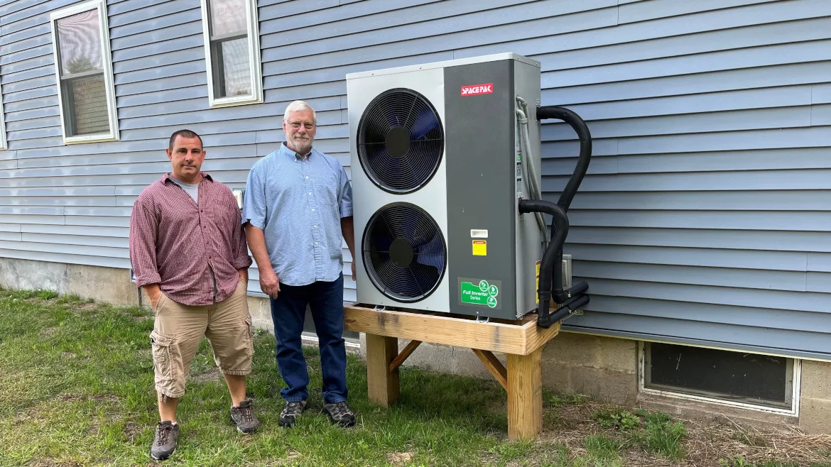
A SpacePak (iLAHP) air-to-water heat pump provides the majority of energy for space heating and most of the domestic water heating. It also provided chilled water for cooling.
The heat pump is supplemented, if necessary, by a 9 KW electric boiler from Electro Industries.
The system controls are relatively simple. In heating mode, the heat pump and electric boiler are operated by a 2-stage setpoint controller that monitors the temperature of the Turbomax tank. Currently, the heat pump turns on in heating mode when the temperature in the tank drops to 100° F, and turns off when that temperature rises to 110° F. The electric boiler is turned on if the temperature in the TurboMax tank drops to 95° F, and off at 110° F. This range of water temperature is suitable for supplying the heat emitters and provides most of the “temperature lift” required to heat domestic water to a delivery temperature of 120° F.
Distributing heat
Space heating is delivered using 10 Myson T6 panel radiators combined with two small areas of floor heating. The latter consists of a small slab-on-grade entry vestibule and a small area under the dining room. All heat emitters operate at the same supply water temperature. There is no need for mixing.
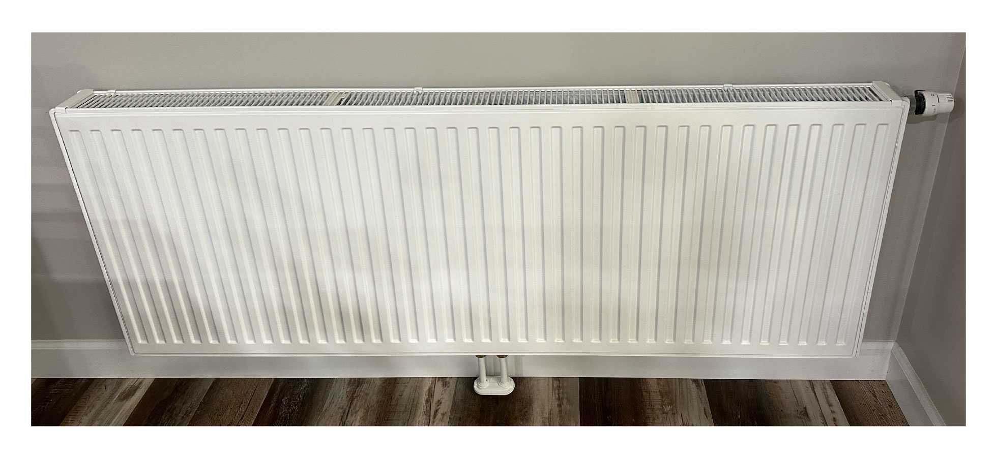
Although the heights and widths vary based on required heat output and available wall space, all the panel radiators use a double water plate, double fins configuration. They were sized around an average water temperature of 110° F at design load conditions. This temperature is well within the efficient operating range of the air-to-water heat pump. Operating the panels at this relatively low temperature increases the ratio of radiant heat output as a percentage of total heat output. Figure 1 shows a typical panel that is approximately 2 feet high, 5 feet wide and 4 inches thick. Each panel is supported by two or three spring-loaded brackets that are fastened through drywall to the wall studs.
Figure 1
The supply and return to each radiator is 1/2-inch PEX-AL-PEX tubing. I like PEX-AL-PEX in these applications because it holds the shape it is bent to, making it easy to neatly install it along floor joists.
The supply and return tube for each radiator rise up through 7/8” diameter holes in the floor that are spaced 2 inches center-to-center. A simple plastic escutcheon plate covers the holes in the floor making for a neat installation. The tubes connect to a dual isolation valve that fastens to the bottom connections on the radiator. This makes it possible to isolate any radiator without affecting the others. I don’t anticipate having to use these valves very much, but they’re ready if ever needed.
Figure 2
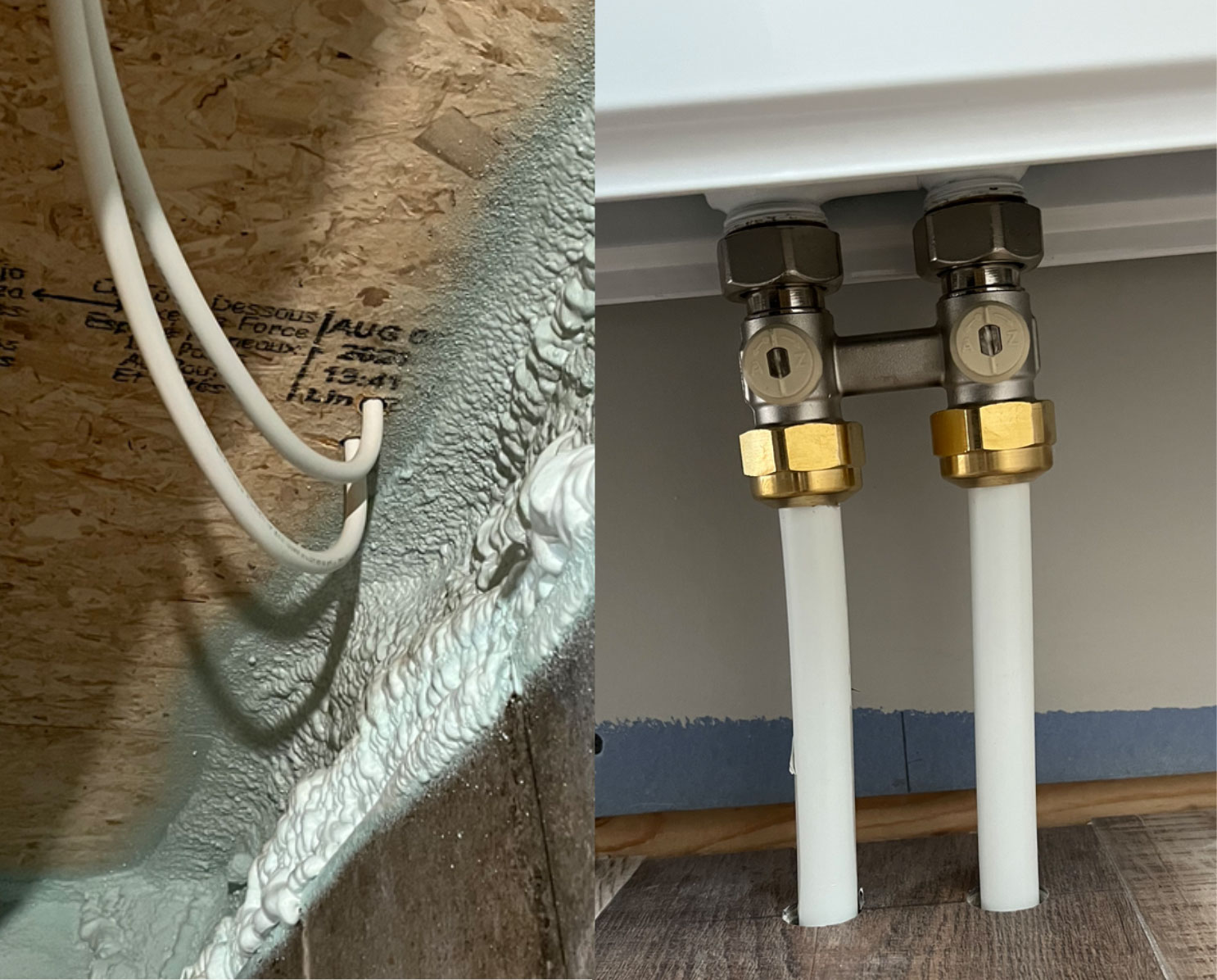
Each radiator comes with an integral valve in the upper right corner. Screwing a Caleffi thermostatic operator onto each valve allows each radiator to operate as an independent zone. That integral valve can also be preset to balance flow through each radiator.
The two flooring circuits are also equipped with thermostatic valves, but for these we used a configuration that connects the valve operator with a wall-mounted temperature adjustment via a capillary tube. A wall-mounted dial with the same markings as the thermostat operators on the radiator valves makes it easy to adjust the output from the two small slabs.
Based on initial operation last winter I don’t expect to have to use supply water temperatures above 110° F (100° F average fluid temperature) under design load conditions. This past February, we maintained indoor temperatures in the low 70s using 90° F supply water temperature.
Extended manifold
Rather than route the PEX-AL-PEX tubing from all those radiators through holes in the floor joists, we created an “extended manifold.” The house had an LVL (Laminated Veneer Lumber) main support girder running down the center of the floor deck. We used one side of this girder to mount 3/4-inch copper tubing for the supply and return “manifolds” that serve each heat emitter circuit, as shown in Figure 3.
Figure 3

Figure 4
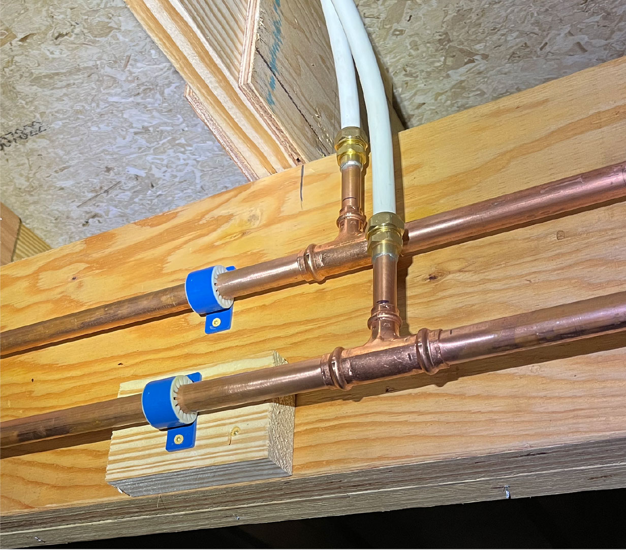
The extended manifold is roughly divided into two halves, with each half running along the LVL girder from approximately the middle of its length. Two 1” copper tubes supply both halves. Figure 4 shows a typical “take-off” for a radiator or floor heating circuit.
Each branch connection is made using a 3/4-inch x 3/4-inch x 1/2-inch press tees. The 1/2-inch side port on each tee transitions to a 1/2-inch PEX-AL-PEX compression fitting.
You’ll notice some short stubs of 1/2-inch copper that are soldered to the brass adapters connected to the 1/2-inch PEX-AL-PEX tubing. This was done because there was no source for 1/2-inch PEX-AL-PEX x 1/2-inch FTG adapters, which, if available, could have been directly pressed to the 1/2-inch side ports on the tees. All this tubing was eventually covered with 1/2-inch thick elastomeric foam insulation.
Hand off
The preheated domestic water leaving the coils in the TurboMax tank is passed to a heat pump water heater, which had been installed in the previous parsonage and was only two years old. It provides the necessary “top off” to bring the domestic hot water delivery temperature from a preheat of about 100° F to approximately 120° F. This heat pump water heater was the sole water heating device in the previous parsonage. In addition to temperature boosting it can provide full DHW backup if the air-to-water heat pump was down for service. It also provides DHW when the air to water heat pump is operating in cooling mode, and keeps the basement cool and dry in summer. Figure 5 shows how the two tanks are connected.
Figure 5
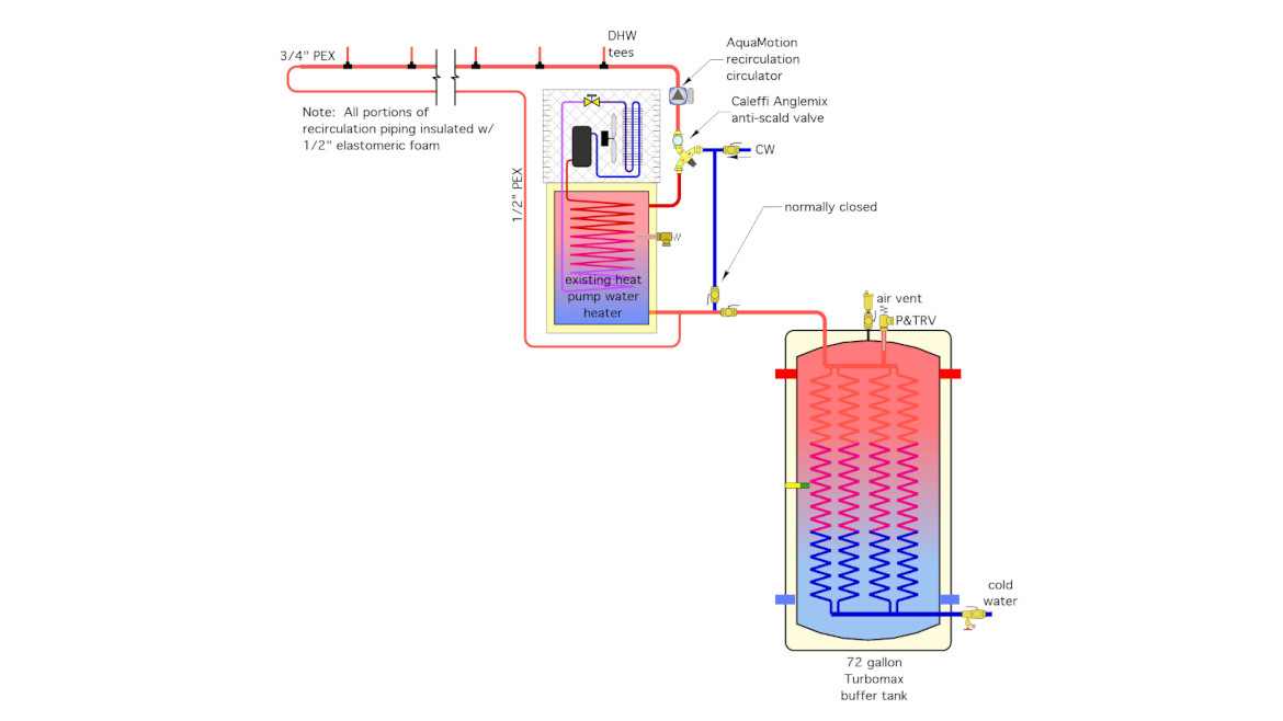
I included an AquaMotion recirculation circulator in the DHW system to ensure prompt delivery at the farthest fixtures in the building. It operates 24/7 at present, but I plan to get it connected through a WiFi-controllable receptacle to set up daily operating times.
Cooling configuration
Although I’m a firm believer in multi-zone heating, I don’t think multi-zone cooling is needed in an average 2,500-square-home. Especially when all areas of the home are occupied, and thus need to be conditioned.
The system uses a single 3-ton rated B&D chilled water air handler for cooling. It’s located in a conditioned and accessible space within the attic trusses, and near the center of the house. It supplies two 8 x 14-inch rectangular trunk ducts that run in opposite directions along the top of the lower truss cords. A 6-inch round branch duct is routed out to each of the 11 ceiling diffusers serving the main floor, and two wall registers serving the finished attic spaces. All branch ducting runs parallel to and between the lower 2x10 truss cords and is insulated to prevent condensation.
Fresh air
The air handler was “customized” by B&D manufacturing to provide a nominal 1200 cfm during cooling mode, and 150 cfm during ventilation mode. The latter is basically a 24/7 operation. Outside air is routed through a heat recovery ventilator and injected into the return side of the air handler at roughly 150 cfm. Thus the air handler and ducting that were designed to deliver cooling also serve to distribute fresh pre-conditioned air through the building regardless of the status of heating or cooling modes. The HRV draws exhaust air from all three bathrooms and can be temporarily set to operate at high speed using wind-up timer switches also located in each bathroom.
Return air flows out of each room through either an open door or, if doors are closed, through return air grills made by Tamarack Technologies. These small grills are cut into the bottom edge of the interior doors. They slip over the cutout and are secured by two screws (see Figure 6).
Figure 6
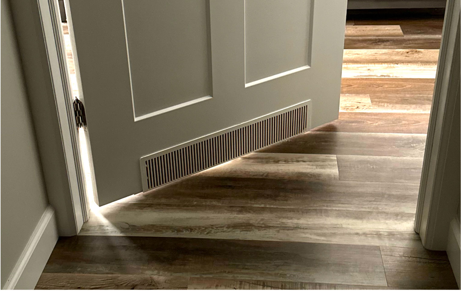
The door grills allow adequate air flow out of the rooms when the doors are closed, and also attenuate light and sound transmission. All return air flow is collected in a ceiling grill equipped with a filter. That grill is located in the ceiling of a hallway, about 3 feet away from the inlet of the air handler. This approach eliminates the need for return air ducting from each interior space while also ensuring proper return air flow, without which neither the cooling system or ventilation system could operate to its full potential.
The heat pump, and if necessary, the electric boiler, maintain the buffer tank between 100° and 110° F year-round. This is necessary to provide space heating in winter, as well as domestic water preheating year-round.
When the system is switched to cooling mode, and the cooling thermostat calls for cooling, the motorized diverter valve reroutes flow from the heat pump to the cooling coil in the air handler. This allows cooling to be the priority load in situations where the buffer tank is calling for heat and the thermostat is calling for cooling at the same time. The controls were set up this way since the heat pump water heater could, if necessary, provide all the DHW needs when a cooling cycle is active. As soon as the cooling thermostat is satisfied, the controls shift focus back to maintaining a heated buffer tank.
When the system switches from maintaining the buffer tank to a call for cooling there’s residual hot antifreeze in the heat pump and several feet of piping leading back to the mechanical room. If this hot fluid was allowed to immediately flow to the chilled water air handler there would likely be a “burst” of hot air from the registers until the heat pump could cool the fluid down. The system prevents this by using a simple setpoint controller that prevents the air handler’s blower from running until the fluid temperature supplied to the coil has dropped to 65° F.
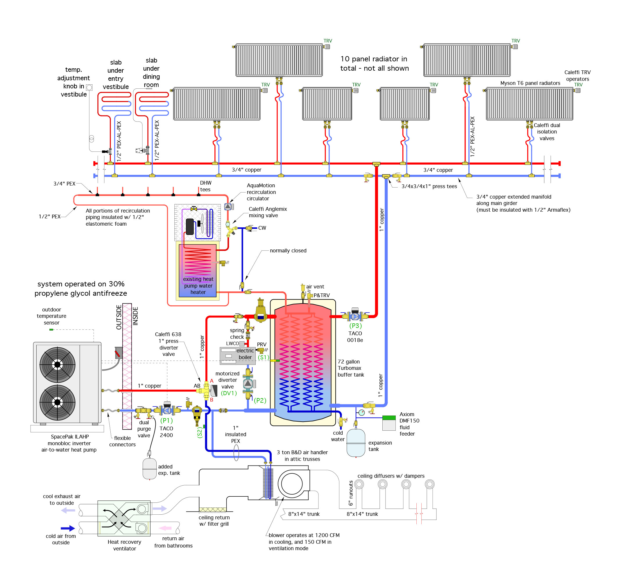
The big picture: Figure 7 shows the overall system piping.
Figure 7
A lesson learned:
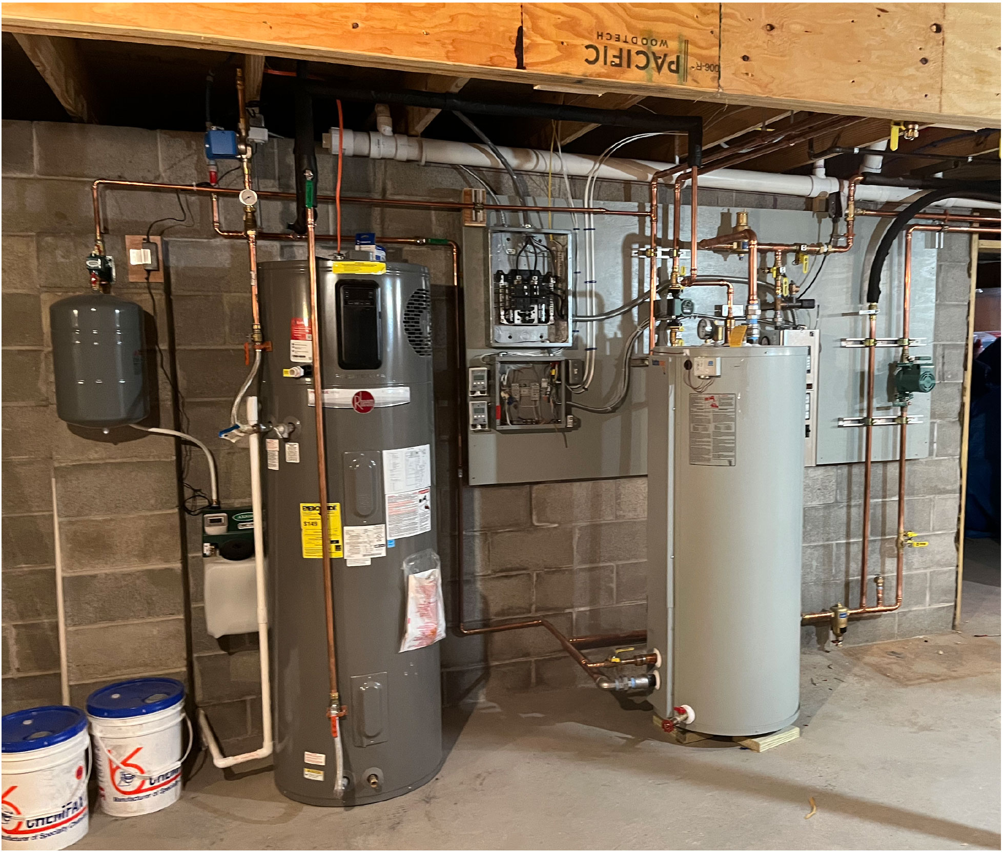
Figure 8
If you look closely at Figure 6 you’ll notice that when the diverter valve is in cooling position (e.g., flow from AB to B), port A is completely blocked. You’ll also see a check valve in the blue pipe just right of the dirt separator. It’s there to prevent cool fluid from migrating toward the buffer tank during cooling operation. The combined action of the diverter and check valve isolate the heat pump piping from the expansion tank during a call for cooling. This caused the pressure relief valve to “dribble” a small amount of antifreeze solution after each cooling cycle ended, and the isolated piping began to warm up — causing fluid expansion without any relief path. This issue is apparent in 20/20 hindsight, but I didn’t see it coming in the original design. Fortunately, it was easily corrected by installing a small expansion tank and connecting it to one of the hose connections on the dual purging valve. The takeaway: Look for portions of an overall piping system that could be isolated under certain conditions, and make sure there’s a relief path back to the expansion tank.
Figure 8 shows the main mechanical space while the system was still under construction, but nearing completion. All electrical loads associated with the HVAC system were supplied from a medicated 100 amp subpanel seen between the two tanks. Control relays, 24 VAC transformers and temperature controllers were organized around a 12-inch x 12-inch junction box below this subpanel. There’s good service access to all components.
Many helpers
This was a special project for me. An opportunity to work with people both within and outside the church to design and help build a new parsonage that should provide years of comfort for our church’s pastor and his family.
The HVAC system would not have come about without the support of many individuals and companies. I want to thank all of the following who helped make this project possible: AquaMotion, Axiom Industries, B&D Manufacturing, Caleffi North America, Chemfax Products LTD, Electro Industries, Myson, Rathe Associates, SpacePak and Taco Comfort Solutions. A special thanks also goes to Dave Dousharm and Mike Bellinger at CNY Pipeworx for putting it all together. They did a great job.
Looking for a reprint of this article?
From high-res PDFs to custom plaques, order your copy today!


