John Siegenthaler: Combining heat pumps with buffer tanks
Consider a buffer tank between the heat source and distribution system.

Whenever a hydronic system is divided into several zones, it’s worth considering a buffer tank between the heat source and distribution system. This is especially true when the heat source is a single-speed “on/off” device rather than a modulating device.
One example is a 4-ton geothermal heat pump supplying several individually controlled panel radiators. Each radiator represents what I call a “micro-zone.” The output of such a zone is likely less than 10%, perhaps even less than 5%, of the heating capacity of the heat source. If you connect several such zones direct to a heat source, even one that can modulate down to say 20% of rated capacity, you’re likely to experience short cycling. This same reasoning holds true for an air-to-water heat pump.
The size of a buffer tank is based on two parameters the designer chooses:
- What is the minimum run time of the heat source that avoids their definition of “short cycle?”
- What is the allowed temperature change of the buffer tank during the minimum on-cycle time?
Once these two decisions are made, the math is pretty easy. The minimum buffer tank size can be determined using Formula 1.
Formula 1:
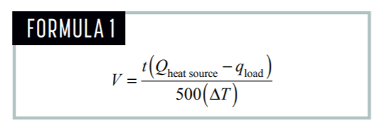
Where:
V = required minimum volume of the buffer tank (gallons)
t = desired duration of the heat source’s “on cycle” (minutes)
Qheat source = heat output rate of the heat source (Btu/h)
qload = rate of heat extraction from the tank (can be zero) (Btu/h)
∆T = temperature rise of the tank from when the heat source is turned on to when it is turned off (°F)
Here’s an example. A designer wants a hydronic heat pump with a rated output of 48,000 Btu/h to operate with a minimum on-cycle of 10 minutes while supplying heat to a towel warmer radiator releasing heat at 2000 Btu/h. The heat pump responds to the buffer tank temperature. It turns on when the buffer tank temperature drops to 100° F, and off when the tank reaches 120°. What is the necessary buffer tank volume to accomplish this?
Just put the numbers into the formula and grab a calculator:
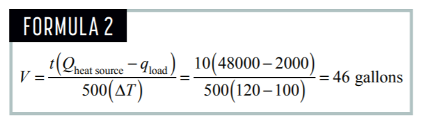
Larger buffer tanks can provide longer heat source on-cycles. They can also allow a narrower temperature change over a specific on-cycle. It’s easy to evaluate the tradeoffs between on-cycle length and tank temperature swing using Formula 1. Large buffer tanks obviously cost more, take up more space in a mechanical room and usually have higher standby heat loss.
Making connections
There are several ways to pipe buffer tanks. They are called “4-pipe,” “3-pipe,” and “2-pipe” configurations. Figure 1 shows all three.
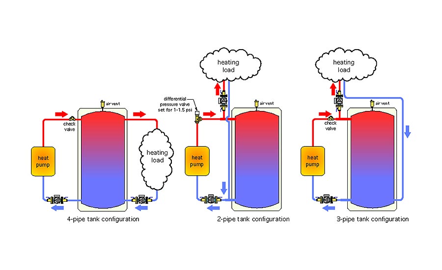 A 4-pipe is the “classic” piping configuration. The heat source adds heat on one side, while the load removes heat from the other side. This piping configuration allows excellent hydraulic separation between the heat-source circulator and the load circulator(s).
One constraint of a 4-pipe configuration is all heat from the heat source must pass through the tank on its way to the load. This isn’t necessarily a problem when the buffer tank temperature is being maintained. However, this arrangement definitely retards heat transfer from the heat source to the load if the tank is allowed to cool down substantially. Be sure to install a check valve on the heat source side of the system to prevent reverse thermosiphoning from the heated tank back through the heat pump circuit when the heat pump is off.
The 2-pipe configuration places the load between the buffer and the heat source. This allows the possibility of passing heat directly from the heat source to the load without having to push that heat through the buffer tank. This allows for faster recovery from setback conditions. One limitation of the 2-pipe configuration is that a differential pressure valve, motorized ball valve or other device that creates a forward-opening resistance of 1 to 1.5 psi that needs to be installed in the heat-source piping to prevent flow that’s returning from the load from passing through the heat source when it’s off. It’s also necessary to keep the tees that connect to the load as close as possible to the tank to allow for good hydraulic separation.
2-pipe buffers should only be used when the heat source is turned on and off based on buffer tank temperature. The reasoning is as follows: If the heat pump flow rate and load flow rate are about the same, there will be very little flow through the tank. This could lead to the heat pump shutting off based on satisfying the space-heating thermostat without adding much heat to the tank. In this scenario, the tank is not “engaged” in the energy flow streams.
However, when the heat pump is controlled directly from the tank temperature, the heat pump should continue to run even after the space-heating thermostat is satisfied, banking heat that’s immediately ready to go to the next zone requesting it.
Meeting in the middle
What do you get when you “average” a 4-pipe buffer with a 2-pipe buffer? Answer: A 3-pipe buffer. This is my preferred arrangement when the heat source is a heat pump. It provides the direct-to-load possibility on the supply side while also forcing return flow through the lower portion of the tank, thus ensuring that the tank’s thermal mass is engaged.
Don’t expect much temperature stratification in a buffer tank connected to a hydronic heat pump. The reason is the relatively high flow rate from the heat pump. Most heat pumps have recommended flow rates of 3 gpm per ton (12,000 Btu/h) of capacity. With water as the working fluid, that results in a ∆T of only about 8°. A typical 4-ton heat pump operating at these conditions would turn over an 80-gallon buffer in less than seven minutes. Those flow rates, especially if introduced vertically into the tank, will create lots of internal mixing. Whenever possible, use horizontal piping connections for flow entering the buffer tank. This reduces internal mixing, allowing cool water at the bottom of the tank to flow into the heat pump.
Putting the pieces together
Figure 2 shows a simple and repeatable template that combines a split-system air-to-water heat pump with a 3-pipe buffer tank and highly zoned distribution system.
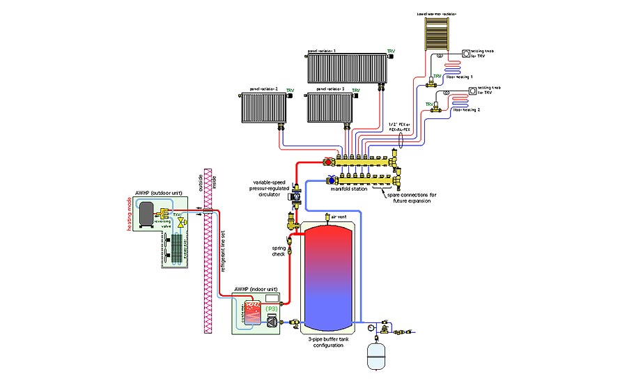
The heat pump supplies a combination of low-temperature panel radiators and radiant floor panel circuits. The flow and heat output of each radiator and radiant panel circuit is regulated by a non-electric thermostatic valve. A variable-speed pressure-regulated circulator automatically adjusts speed based on the status of these valves. The heat pump is turned on an off to maintain the water temperature at the middle of the buffer tank between 100° and 110°.
In addition to buffering the heat pump against short-cycling, the tank provides hydraulic separation between the heat pump’s internal circulator and the variable-speed distribution circulator. This system leverages many modern concepts that work together for high energy efficiency, reliability and unsurpassed comfort. Keep it in mind for a future project.
Looking for a reprint of this article?
From high-res PDFs to custom plaques, order your copy today!


