Hydronics Workshop | John Siegenthaler
Creating a complete system to provide space heating, cooling, DHW and fresh air ventilation
Combined elements
My family has attended Bethel Baptist Church in Prospect, New York, for many years. The church was founded in 1976 by a small group who pooled their resources to purchase a two-classroom school building that was built in the 1930s.
That building has since been expanded in several phases to include a new sanctuary, Sunday school wing, and multi-purpose room. All the additions have slab-on-grade floor heating supplied by oil-fired boilers. A 10-ton air-based cooling system was also added over time. In short, the church’s public facilities are in good shape and serve the needs of the membership well.
The original purchase included several acres of land. Some of it was used to site a parsonage, which was built in 1978. At that time, the church decided to purchase a double-wide mobile home and place it over a new 24x48-foot basement.
Since its original installation, the double-wide unit has also undergone many changes, some of which were planned (a bedroom and bathroom addition) while others came of necessity (e.g., extensive repairs following a broken water pipe that flooded the entire building), new roof, new windows, new cabinets — the list goes on…
After 45 years in upstate New York weather, several repairs from a variety of well-intentioned volunteers, along with the wear and tear associated with housing many adults and kids, the double-wide mobile home had “done its time.” It had reached a point where major and expensive repairs were needed. Evidence of mold, and related indoor environmental conditions added to concerns.
Fortunately, one portion of the original project — the basement foundation — remained in excellent condition.
A proposal to remove the mobile home portion of the building, and reconstruct a new home on the original foundation was developed, presented to the membership and approved. My role was to design the new structure over the existing foundation and develop a plan for the HVAC system.
The “kid in a candy store” analogy comes to mind…
Plans for the building were developed during the COVID period, approved by the membership, and construction began in October of 2022. Figures 1 and 2 show the exterior of the new home (while still under construction).
Figure 1
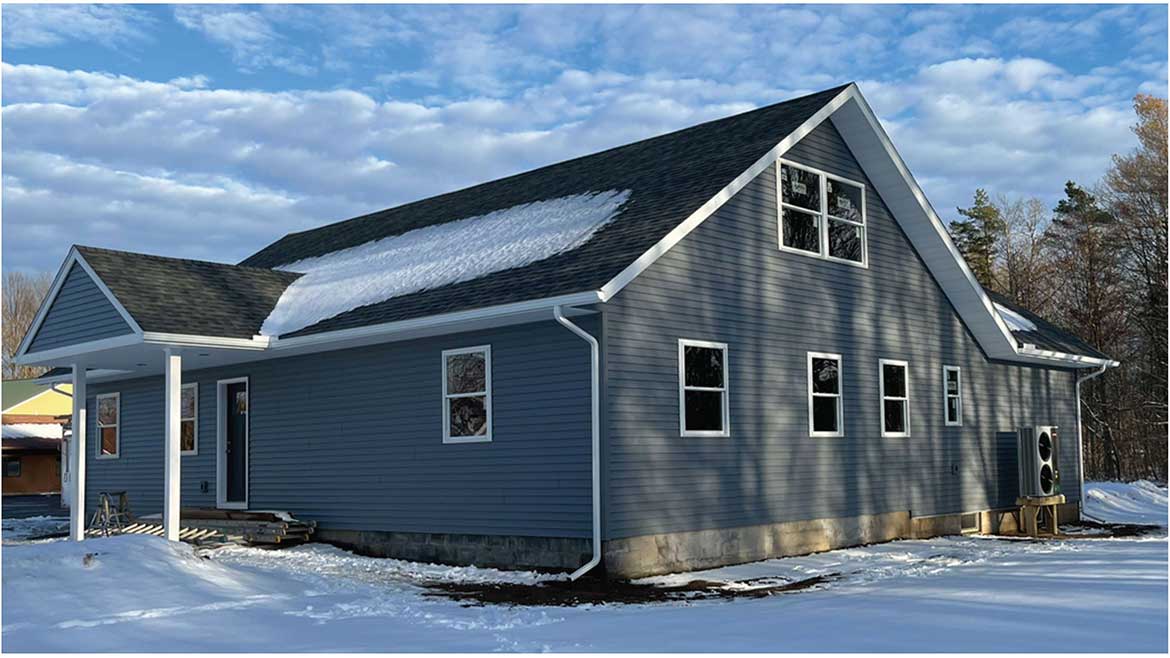
Figure 2
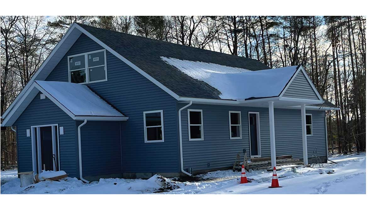
Figure 3 shows a structural section for the building.
Figure 3

The home provides just over 2,600 square feet of living space, including 5 bedrooms and 3 full bathrooms. It uses 24-inch on-center inline framing and attic trusses. The entire framed structure is insulated with spray polyurethane foam, which resulted in a design heating load of about 34,000 Btu/h at an outdoor design temperature of -5° F. In short, it’s an energy-efficient, strong, fast-build, low-maintenance and functional structure. Nothing aesthetically elaborate, but plenty of usable low-maintenance space that will provide excellent year-round comfort and a healthy interior environment.
Mechanicals
I could go into more details about the building, but suspect that most readers are more interested in the HVAC system, so let’s get into it.
The overall objective was to create a complete HVAC system, rather than just a heating + cooling system. The system would provide space heating, cooling, domestic hot water, and fresh air ventilation.
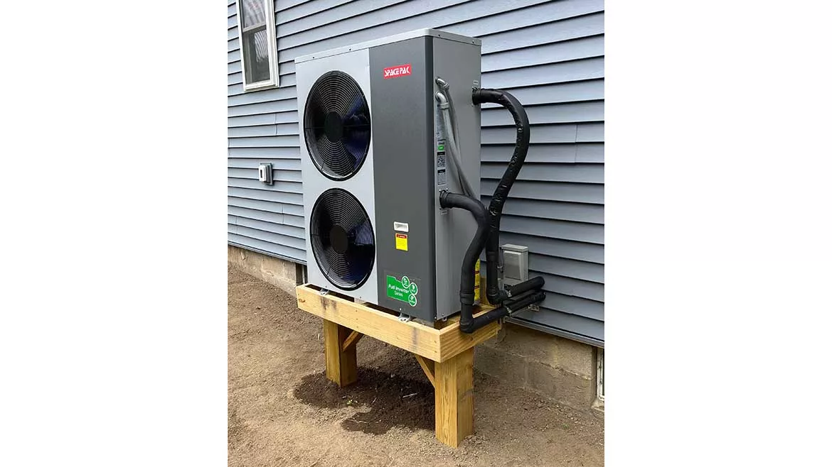
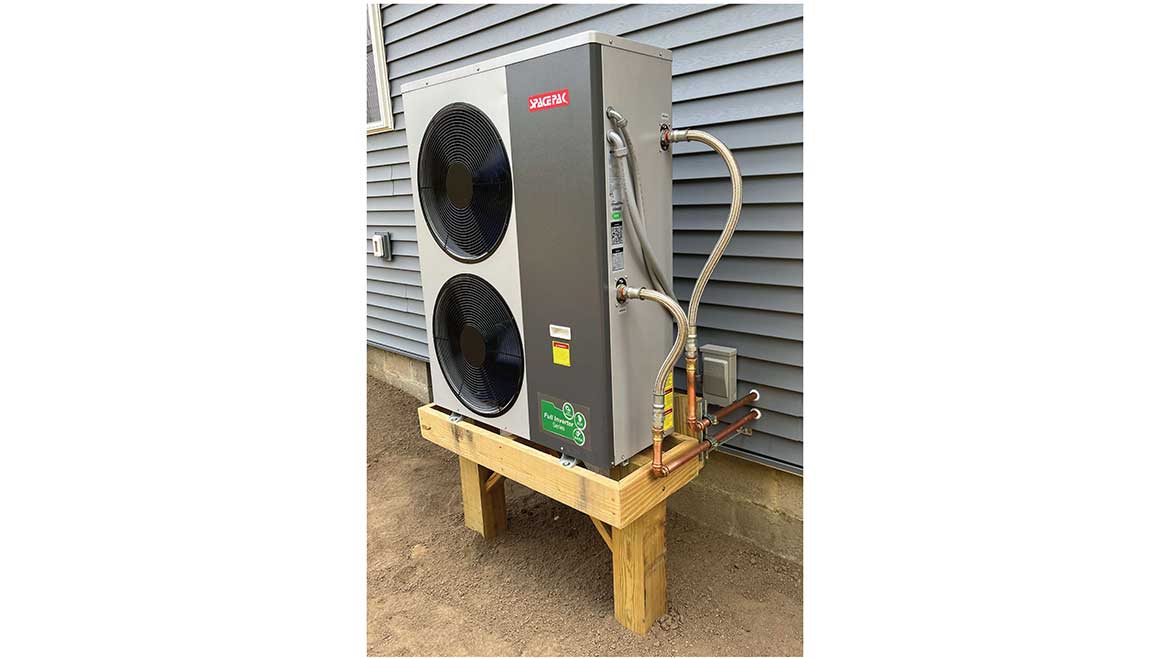
The primary source for heating and cooling energy was a SpacePak “iLAHP” air-to-water heat pump (iLAHP is short for low ambient heat pump equipped with an inverter compressor). Figure 4 shows the unit mounted on a raised platform to keep it above snow.
Figure 4
This heat pump is nominally rated at about 4 tons (48,000 Btu/h) heating capacity when supplying 113° F fluid while operating at an outdoor temperature of 25° F. It’s capable of at least 5 tons of output at higher outdoor temperatures. It can also operate at outdoor temperatures as low as -22° F, albeit at significantly lower heating capacity and COP.
The photo in Figure 4 shows the piping between the unit and building, but prior to the installation of piping insulation. One of the watertight conduits contains the line voltage wiring while the other contains the low voltage wiring. The service disconnect is located on the wall adjacent to the piping penetrations.
The mounting frame is supported by two treated 6x6 posts resting on concrete bases below the frost line. This frame also braced the building framing using two 3/8-inch threaded steel rods, one near each corner of the frame. These prevent the assembly from being buffeted by turbulent winds.
The copper tubing is secured to the channel strut using rubber-lined clamps to dampen any vibration.
The heat pump piping, which is now covered with 1/2-inch wall thickness elastomeric foam insulation, connects to a 1-inch Caleffi motorized 3-way ball valve. During heating mode, this valve directs flow from the heat pump to a 72-gallon Turbomax buffer tank in the basement. In cooling mode, it directs flow to a nominal 3-ton chilled water coil in an air handler that’s mounted in a conditioned and accessible space within the roof truss.
The air handler supplies trunk ducts that are also routed through fully conditioned space within the roof trusses. Several ceiling diffusers, each with adjustable dampers, are supplied through 6-inch round metal ducting that runs parallel to and between the bottom cords of the trusses and drop to ceiling diffusers.
The system uses a 72-gallon TurboMax tank as a buffer for space heating and as a domestic water preheater. The tank has internal copper coils through which domestic water passes whenever hot water is required at a fixture. The temperature of the tank is maintained between 95° and 105° F so that domestic water is preheated as it passes through these coils. The preheated water is “topped off” in temperature by a heat pump water heater that was reused from the original structure.
Figure 5 shows a partial schematic of how the heat pump connects to the 3-way motorized valve, the TurboMax tank and the air handler.
Figure 5
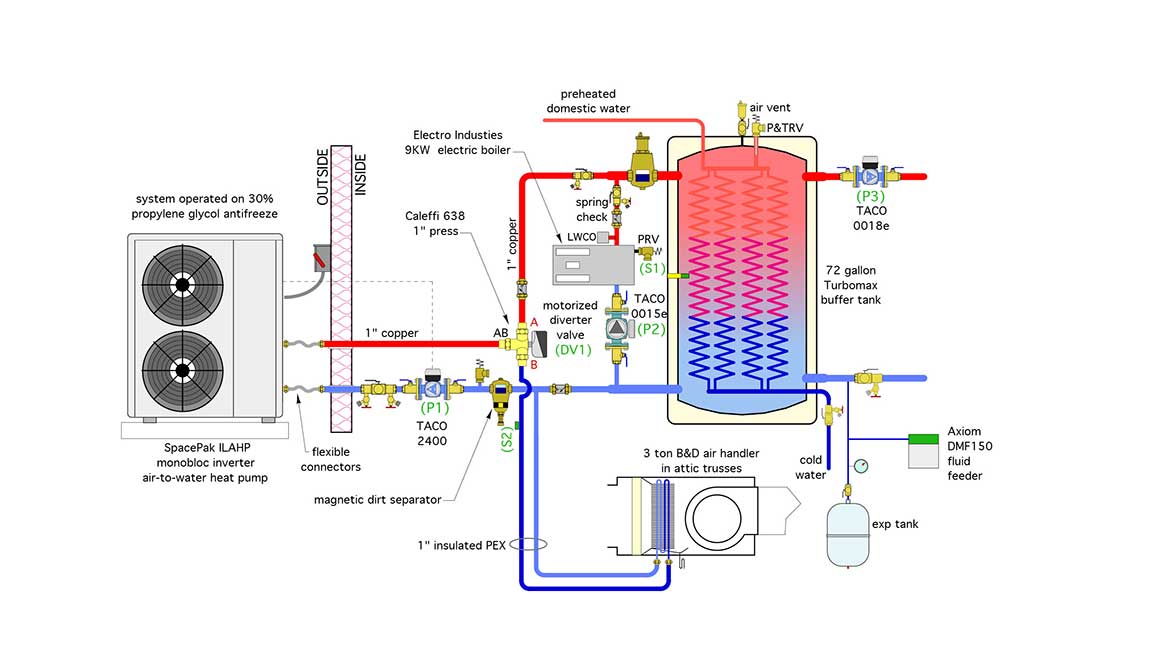
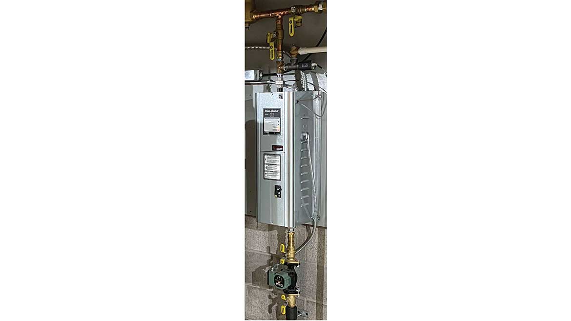
The system also has an Electro Industries 9KW electric boiler to provide supplemental and backup for the heat pump (see Figure 6). It’s piped in parallel with the heat pump. It can operate simultaneously with the heat pump or as the sole heat source.
Figure 6
In cooling mode, the diverter valve directs the chilled antifreeze fluid coming from the heat pump to a B&D Manufacturing chilled water air handler. The heat pump varies the speed of its compressor to maintain a chilled fluid outlet temperature of 50° F.
Other components include an Axiom fluid feeder, Caleffi air and dirt separators and three Taco circulators.
The head loss of the heat pump and air handler coil, combined with the flow requirement for the heat pump, required a relatively powerful circulator (Taco 2400). The electric boiler uses a much lower power Taco 0015e circulator (44 watts). The entire heating distribution system operates on a single Taco 0018e variable-speed pressure-regulated circulator, which is also rated at 44 watts input power at full speed. The 0018e runs 24/7 during the heating season, modulating its speed based on proportional differential pressure control in response to the flow requirements of the heat emitters.
The piping concepts used are relatively simple, scaleable and repeatable. We’ll get into the “weeds” on how the system operates in part two.
Looking for a reprint of this article?
From high-res PDFs to custom plaques, order your copy today!


