Hydronics Workshop | John Siegenthaler
Build what you need: Availability and customization of heat pump systems opens doors of possibilities

Lead image courtesy of MTStock Studio / E+ / Getty Images
The availability of heat pumps has made it possible for those who design and install hydronic heating to expand their offerings to include cooling.
One of the simplest approaches uses a single air handler with a chilled water coil, to supply a ducted forced-air distribution system. In “average” houses this approach, which provides single zone cooling, can be combined with multi-zone hydronic heating. For example, a single air handler rated for nominal 3-tons of cooling could be combined with a heating distribution system that supples 8 panel radiators, each with their own thermostat control valve. We’ve discussed this approach is several previous Hydronics Workshop columns.
When one isn’t enough
There are situations where clients want zoned cooling, or want to use fan-coil to operate for both heating and cooling. This is certainly possible, albeit at a higher level of complication and cost relative to single zone cooling.
Figure 1 shows two piping options for such a system. Both use a simple homerun style distribution system serving 5 console fan-coil units.
FIGURE 1
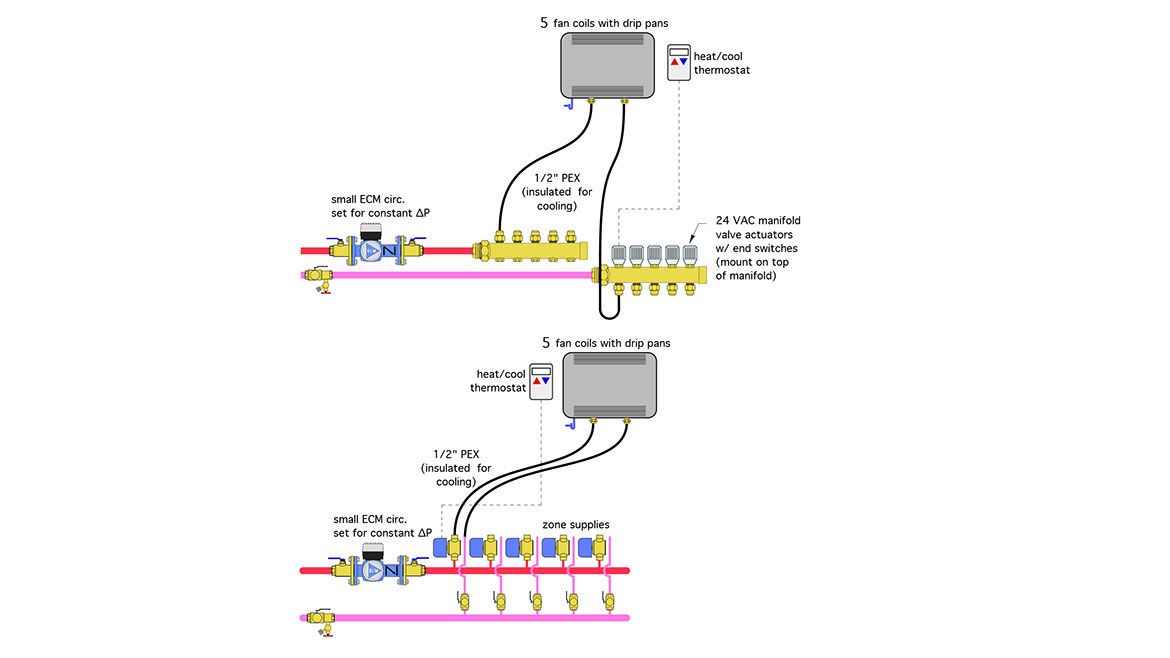
One version of the piping uses zone valves, the other uses manifold valve actuators. Each zone is operated by a 24VAC heat/cool thermostat, (we’ll get into the wiring of that thermostat shortly).
Zone valves typically provide higher Cv values relative to manifold valves, and thus create less head loss in zones that require upwards of say 2 gpm flow. Some zone valves can be configured with tailpieces that connect directly to PEX tubing on one side, and press fit to copper tubing on the other.
If manifold valve actuators are used be sure that a) the manufacturer endorses their use with chilled water cooling, and b) be sure they are mounted on top of the manifold to prevent any condensate from running down - and possibly into - the actuator body.
A variable-speed pressure-regulated circulator is used in each approach. It automatically adjusts speed as the zone valves or valve actuators turn on an off.
Necessary connections
One of the common approaches for wiring multi-zone hydronic heating systems is to use a multi-zone relay center. Figure 2 shows a “generic” and simplified wiring for such a controller.
FIGURE 2
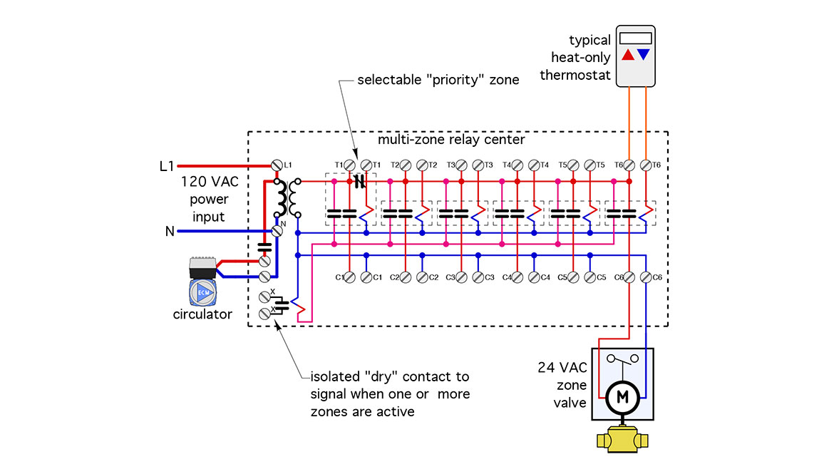
A 24VAC output for each thermostat is provided for each set of terminals along the top of the controller. A corresponding 24 VAC output for powering each zone valve is provided along the bottom. An isolated “dry” contact (x,x) that closes when any one or more zones turns on can be used to “signal” the balance of system that a zone is active. These multi-zone controllers also have a line voltage powered contact to operate a circulator when any zone is active.
In this generic layout, each zone is turned on and off by a double pole single throw (DPST) relay. One contact of the relay passes 24 VAC to the zone valve. The other contact passes 24 VAC to the isolated relay for the (x x) terminals.
Most of these controllers also have the option of making one zone the “priority zone.” When it is active the other zones are temporarily turned off. This allows the full output of the heat source to be directed to the priority zone. The priority zone is typically used to direct heat to an indirect domestic water heater. Many modern controllers also have a “time out” feature that would either turn on the other zones if the priority zone has been active for a specific time (30-60 minutes is typical), or toggle the priority zone on and off with the non-priority zones to ensure that all active zones will receive some heat within a time that prevents potential freezing under extreme conditions.
Although there are many makes and models of multi-zone controllers for hydronic heating, there are - to my knowledge - none that accommodate thermostat inputs for both heating and cooling. This presents a challenge when systems such as shown in figure 1 need to operate multiple zones in both modes.
Temporary work around
I fully expect that multi-zone controllers that can operate in both heating and cooling modes will be developed, especially given the rising interest in heat pumps as the primary heat (and cooling) source for hydronic systems.
In the meantime, consider the approach shown in figure 3.
FIGURE 3
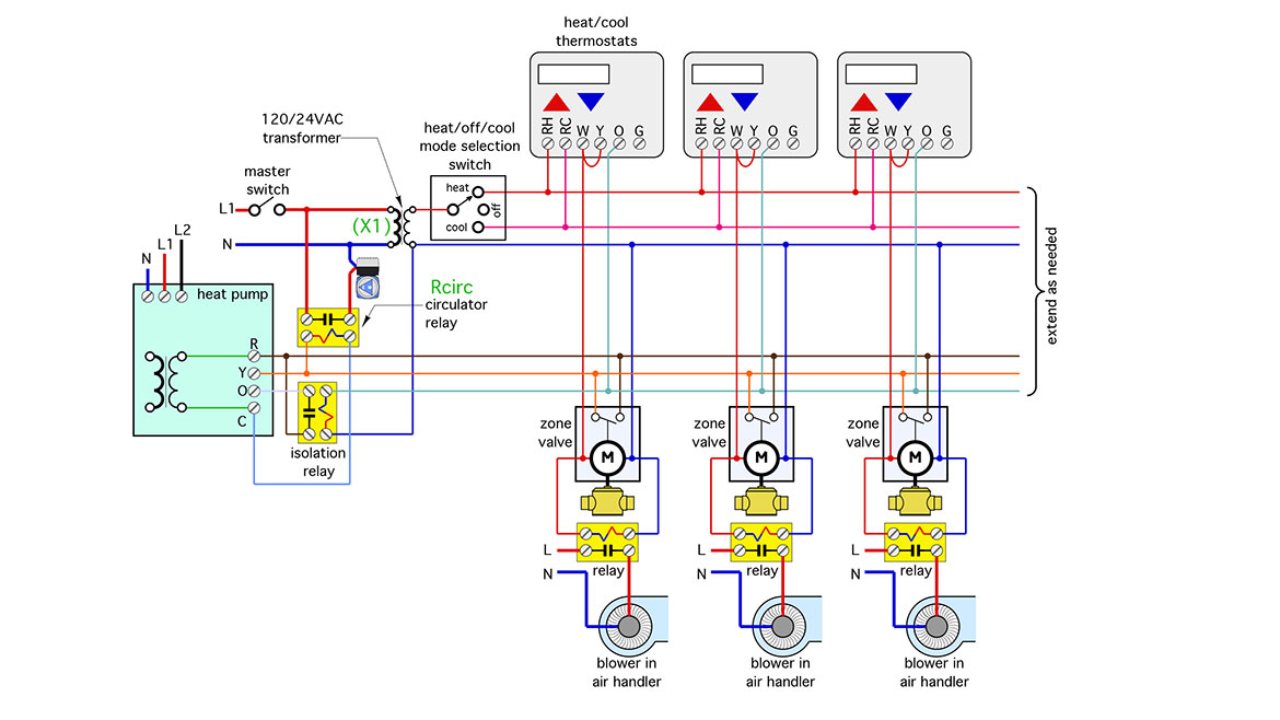
This is one of several ways to wire several single stage heat/cool thermostats to operate their associated zone valves, fan-coil, and heat pump. Other wiring methods depend on the compatibility of the thermostat and internal controls in each fan-coil. The approach shown in figure 3 is as “generic” as possible to accommodate a range of thermostats and fan-coils.
Heating mode
Starting in the upper left corner, whenever the master switch is closed the transformer supplies 24 VAC to a heat/cool/off mode selection switch. That switch sets the operating mode (e.g., heating or cooling) for all the zones. When set for heat the switch supplies 24VAC from the transformer (X1) to the (RH) terminals on all thermostats. When set for cooling 24 VAC from the same transformer passes to the (RC) terminal in each thermostat.
Many heat/cool thermostats are supplied with a factory installed jumper between the (RH) and (RC) terminals. For the wiring shown in figure 3 it’s important to remove this jumper so that the (RH) and (RC) terminal are electrically isolated.
When the heat/cool/off mode selection switch is set for heating, and one of the thermostats calls for heat, 24VAC pass from that thermostat’s (RH) terminal to its (W) terminal. That 24VAC signal then passes to the associated zone valve or manifold valve actuator. It also powers a relay (shown below the zone valve). The relay contacts close to pass line voltage (120VAC) to the blower in the fan-coil. Some air handlers require 240 VAC. In that case the relay needs to have two poles.
A short time after the zone valve receives power the end switch closes completing a separate circuit between the heat pump’s (R) terminal and its (Y) terminal. This signals the heat pump to start it’s compressor. The heat pump will begin operating in heating mode.
24 VAC from the heat pump’s (Y) terminal also passes through the coil of relay (Rcirc). The other side of that relay coil connects to the common (C) terminal in the heat pump. The contacts in relay (Rcirc) close to apply line voltage to the circulator. Keep in mind that the 24VAC supplied from the heat pump’s internal transformer is completely separate from the 24VAC supplied from the transformer label (X1).
Cooling mode
When the master selection switch is set for cooling, and one of the thermostats calls for cooling, 24VAC pass from the thermostat’s (RC) terminal to its (Y) terminal. Because the (W) and (Y) terminals in each thermostat are jumpered, 24VAC also powers the actuator on the associated zone valve and the blower relay for that zone. The blower relay contacts close to pass line voltage (120VAC or 240 VAC) to the blower motor in the fan-coil.
A short time after the zone valve receives power the end switch closes completing a separate circuit between the heat pump’s (R) terminal and its (Y) terminal. This signals the heat pump to start it’s compressor. But wait! Isn’t that the same as what was just described for heating mode?
Yes, but with an explanation.
When the thermostat is set for cooling, and passes 24VAC to it’s Y terminal, it also passes 24 VAC to its (O) terminal. The (O) terminal is what energizes the heat pump’s refrigerant reversing valve to enable cooling operation.
Follow the lines from any of the thermostat (O) terminals and you’ll see that the 24VAC they pass energizes the coil in an isolation relay near the left side of the schematic. The contacts in this isolation relay complete a circuit between the heat pump’s (R) and (O) terminals. As soon as the (O) terminal in the heat pump receives 24VAC the refrigerant reversing valve actuates to cooling mode.
The isolation relay is needed because the 24VAC signal that goes to the thermostats, and powers the zone valves, comes from a transformer that’s completely separate from the transformer inside the heat pump. It’s important not to get the wiring associated with these two transformers inadvertently crossed. When multiple transformers are used pay close attention to where any 24VAC signal in the system is coming from, (e.g., usually some “R” terminal, and where it’s going (e.g., usually a “C” terminal), after passing through some electrical load device, such as a relay coil or zone valve actuator.
Although the system shown in figure 3 shows has three zones, the wiring diagram could easily be expanded to the right to include more zones. The limit is primarily based on the VA (volt•amp) demand of the zone valves relative to the VA rating of the transformer used. Keep the total VA demand slightly under the transformers VA rating and all is well.
Hardware choices
Notice that there are several horizontal lines in the schematic of Figure 2 that connect to terminals on each thermostat and each zone valve. For example, the red horizontal line connects to the (RH) terminals on all the thermostats, and the orange horizontal line connects to one side of the end switch in each zone valve. The colored dots indicate an electrical bond between each horizontal line, and the shorter lines of the same color that run out the various terminals. From an electrical standpoint this means that all those shorter lines of a given color are connected in parallel. Physically, if you had all the red line wires that go to the (RH) terminals in your hand, you could just join them with a wire nut. It would work, but it’s a bit “messy” and arguably harder for a future service technician to figure out.
A better approach to keep all the parallel wiring segments organized is to use some simple terminal strips such as shown in figure 4.
FIGURE 4
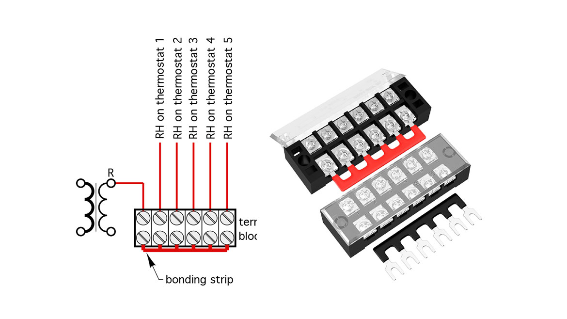
This type of terminal strip is available from many online sources. The small (red) bonding strip slides under the terminal screws on one side of the strip to connect them all together electrically. With this bonding strip installed, the red wire coming from the transformer could go to one of the terminals and any other wires connected to the other screws would be bonded to it. Those other wires would be from the (RH) terminals on all the thermostats. Another terminal strip could be set up the same way for all the pink wires, another for the orange wires, etc. These terminal strips only cost about $2 each, and have plastic “caps” that prevent other stray wires from making contact with the screws
The relays
The bright yellow boxes in figure 3 are small, single pole, general purpose relays. Figure 5 shows one example, which has single pole / double throw (SPDT) contacts. these relays have male quick connecter terminals.
FIGURE 5
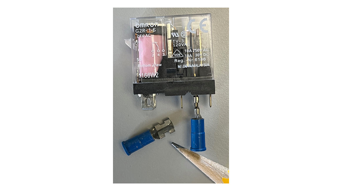
The relays all have coils that operate on 24VAC, and contacts capable of switching line voltages at currents up to 10 amps, which is typically above what’s required in most residential and light commercial systems. These relays are also relatively inexpensive at around $8 each, and substantially less if purchased in lots of 10.
Customized
The wiring diagram shown in figure 3 is - in essence - a custom controller that coordinates with multiple heat/cool thermostats to operate zoned fan-coils in both heating and cooling. It operates an air-to-water (or geothermal water-to-water) heat pump as needed in both modes. It uses simple and inexpensive hardware to create the necessary control logic and keep the wiring organized. It’s also designed to be a simple and “goof-proof” as possible.
Earlier in the column I mentioned that this is one of multiple ways to control multiple heating and cooling zones. Variations of this approach are possible depending upon the internal electrical design of the fan-coils, and how that wiring could coordinate with the specific thermostats used. For example, some fan-coils may have a normally open dry contact that could be used in lieu of the end switches in the zone valves, to signal the heat pump to operate.
After selecting specific products for the thermostats and fan-coils create the wiring diagram and pay close attention to keeping 24VAC circuits powered by different transformers from being inadvertently electrical interconnected. Keep in mind that all the zones must operate in the same mode and any given time, as determined by the master mode selection switch.
Finally, a “nudge” to manufacturers… The North American market for hydronic heat pumps is expanding. Residential and light commercial systems are being built for hydronic heating and cooling. The industry needs products that support this trend. Examples include zone controllers for heating and cooling, insulation shells for circulators and other components, pre-insulted PEX, PEX-AL-PEX, PERT tubing, and controllers for managing smaller radiant cooling systems. Opportunity and willing customers await.
Looking for a reprint of this article?
From high-res PDFs to custom plaques, order your copy today!


