The Glitch & The Fix: Backed-up Btu

The Glitch:
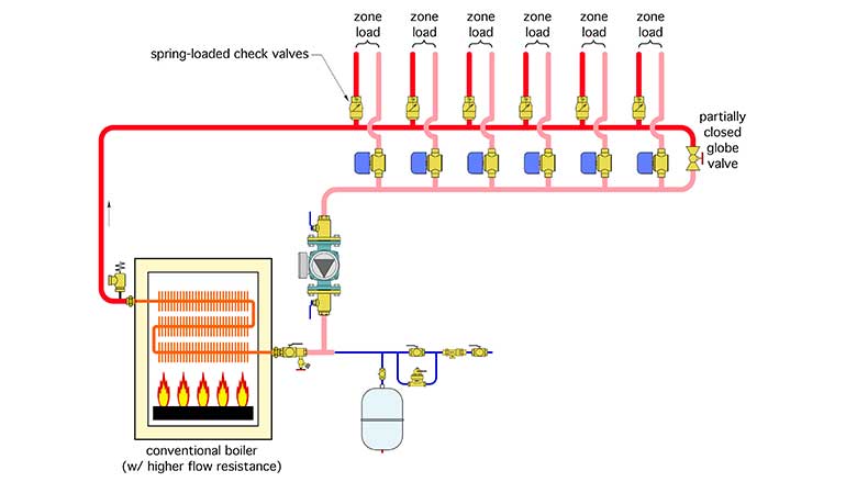
An installer sets up a single-stage copper tube boiler with a zoned distribution system as shown in Figure 1. To keep things simple, he uses the same size piping for the headers and all the distribution circuits. The distribution system operates at water temperatures where sustained flue gas condensation will not be an issue. To prevent heat migration, he installs a spring-loaded check valve at the beginning of each zone circuit, just above the header. To control differential pressure he installs a partially open globe valve across the ends of the headers. He sets the globe valve for one half turn open.
Can you identify and describe at least 5 details in this system that should be changed?
► FIGURE 1
The Fix:
Figure 2 shows one approach that eliminates these issues.
► FIGURE 2

Here’s what’s wrong and how to correct it:
- Copper tube boilers need adequate flow whenever they are firing. There’s no assurance that a single operating zone would provide that flow. Adequate flow can be maintained by hydraulically separating the boiler from the distribution system using a pair of closely spaced tees, and providing a dedicated boiler circulator.
- The partially closed ball valve at the right end of the headers in not a reliable way to control differential pressure across the headers. A properly set variable speed, pressure-regulated circulator can manage this task. There’s no need for the “bypass valve” at the end of the headers.
- Headers should always be generously sized to minimize pressure drop along the length of the header. This plays a part in providing hydraulic separation between the load circuits. A general rule is to size the headers so that the flow velocity at the entry of the header does not exceed 2 feet per second assuming all zones are operating.
- The system circulator in Figure 1 is pumping toward the point where the expansion tank connects. Always pump away from this connection point.
- It’s never a good idea to install check valves near fittings that creates high turbulence. This is the case with the check valves shown in the glitch drawing. There should always be at least 12 diameters of straight piping upstream of any check valve to calm turbulence that otherwise will cause the check valve to rattle. However, heat migration in this system can be eliminated by simply installing the zone valves on the supply side of the zone circuits. Do this and there is no need of installing the check valves.
- Purging valves on each zone circuit are missing in the glitch drawing. They are shown in the fix.
Figure 3 shows an alternate system configuration where a hydraulic separator replaces the air separator and the closely-spaced tees. It also provides dirt separation for the system, and, if it’s equipped with a magnet, it also provides magnetic particle separation. The latter is a good idea whenever a circulator with an ECM motor is used in the system.
► FIGURE 3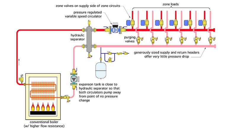
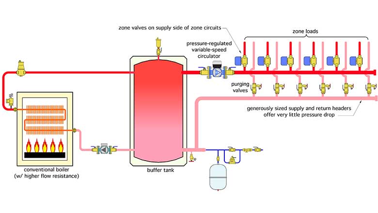
It’s also possible to use a buffer tank in place of the hydraulic separator. Doing so would lengthen the boiler’s cycling time, likely boosting its seasonal efficiency and increasing the life of its internal components. A schematic for this configuration is shown in Figure 4.
► FIGURE 4
Looking for a reprint of this article?
From high-res PDFs to custom plaques, order your copy today!


.jpg")
