The Glitch + The Fix: Indirect bottleneck

The Glitch:
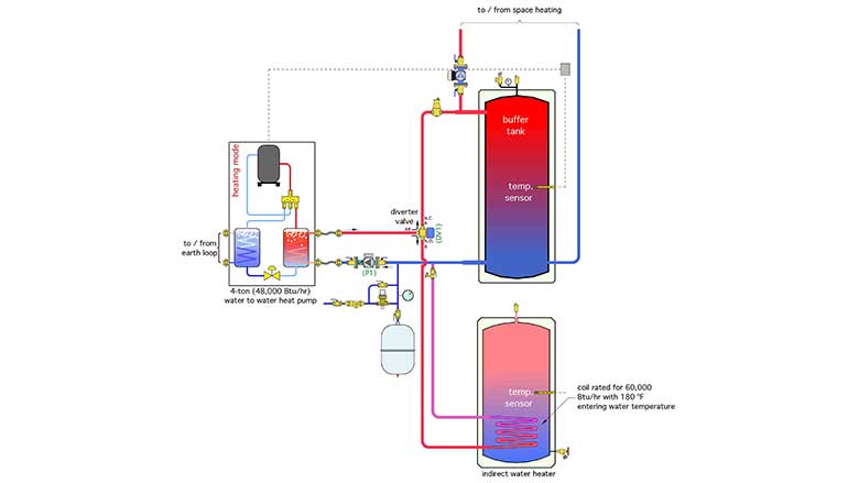
An installer is asked to provide a 4-ton-rated (48,000 Btu/h) geothermal heat pump system that can provide space heating and domestic hot water. The client doesn’t want cooling for the initial installation but would like the possibility of adding it in the future. The installer selects an indirect water heater with a coil rated to deliver 60,000 Btu/h to the tank when supplied with 180° F water from a boiler. He also includes a buffer tank in the system to protect the heat pump against short cycling when supplying a zoned distribution system. A motorized diverter valve is used to route the heated water from the heat pump to either the indirect water heater or the buffer tank. A schematic for the installation is shown in Figure 1. Can you describe what issues might arise with this approach? What would be a simpler design?
What’s wrong?
Most current generation heat pumps can only operate at water temperatures up to approximately 125° F. A few can operate up to 130°-140°, but at significantly reduced heating capacity and COP during cold outdoor conditions.
The coil of the indirect water heater, rated for 60,000 Btu/h dissipation when supplied with 180° F water, will have a much lower heat transfer rate when supplied with 125° F — perhaps 20% to 30% of its rated capacity.
This sets up a heat transfer “bottleneck.” The heat exchanger coil in the indirect, operating at an inlet temperature of only 125° F, cannot keep up with the heat output of the heat pump. Within a few minutes, the heat pump will be shutting itself off due to high temperature or high refrigerant pressure. It my attempt to restart a couple of times, but the problem will reoccur, leading to a “hard lockout.” Manually restarting the heat pump will just set up the same scenario.
The Fix:
The fundamental problem with the system described above is the lack of heat transfer capacity between the heat pump and domestic water. One solution is to use a generously-sized external stainless steel heat exchanger mounted at the side of the buffer tank, as shown in Figure 2.
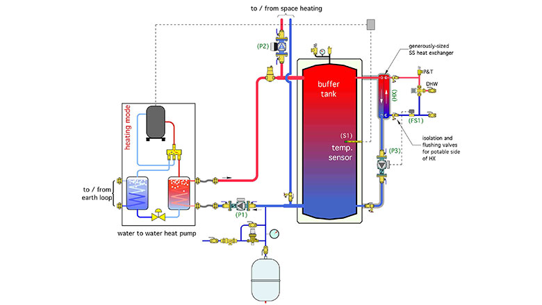
Whenever a draw for domestic hot water reaches or exceeds 0.7 gpm, a flow switch on the cold water supply to the heat exchanger closes. This turns on a small circulator (P3 in Figure 2), which routes water from the top of the buffer tank through the primary side of the heat exchanger. The incoming cold domestic water absorbs heat on the secondary side of the heat exchanger. The high surface area to volume ratio of the heat exchanger, combined with its proximity to the tank, allows it to reach steady state conditions in only a few seconds, effectively making it an “instantaneous” water heater.
A suggested sizing criterion for the heat exchanger is an approach temperature difference no higher than 5° F when operating at the minimum temperature of the buffer tank. Thus, a tank with 125° F water at the top, could yield 120° F domestic hot water.
The heat exchanger and piping back to the tank should be insulated to minimize heat loss.
If higher water temperatures are required, the DHW outlet of the heat exchanger could be piped to the inlet of either a tank-type water heater or an instantaneous water heater.
This design also allows a single tank to provide buffering for the space heating load and heated thermal mass for DHW.
When the time comes to add cooling, the system shown in Figure 3 is one possible approach.
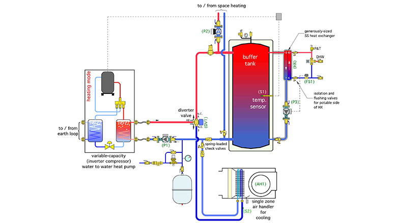
A chilled water air handler has been added to the system. During cooling operation a motorized diverter valve directs chilled water from the heat pump to the coil in the air handler.
Because the buffer tank is not used to store chilled water, and assuming that the cooling load is significantly less than design heating load, this approach should use either a 2-stage heat pump, or a one with a variable speed compressor. The objective is to reasonably match the cooling capacity of the heat pump to the cooling capacity of the air handler, when operating with a chilled water temperature in the range of 45° to 55° F.
A “priority” control scheme can be used to temporarily interrupt cooling operation to maintain the buffer tank temperature high enough to provide DHW at all times.
Looking for a reprint of this article?
From high-res PDFs to custom plaques, order your copy today!


.jpg")
