The Glitch + The Fix: This almost got built

The Glitch:
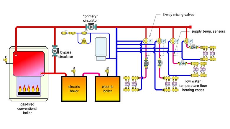
A recent inquiry involved a heating system for a school in which two electric boilers were being added to supplement the output of a gas-fired cast-iron boiler, and take advantage of low “off-peak” electrical rates. The load was four zones of low water temperature floor heating. The designer planned to operate the gas-fired boiler at temperatures high enough to avoid sustained flue gas condensation and to install a “bypass circulator” as another means of boosting boiler inlet temperature. A 3-way motorized mixing valve would be used to reduce the supply water temperature in each of the four zones. The proposed schematic for the modified system is represented (very closely) in Figure 1. Can you spot several details that would be better handled through an alternate design?
The Issues:
- Never pipe boilers or other hydronic heat sources in series. There is no upside, just multiple downsides, such as not being able to remove one boiler for service without temporarily changing the piping to keep the system operating. Or, in the case of mod/con boilers or heat pumps, lowering the efficiency of the downstream heat sources due to higher inlet water temperature. Flow of heated water through inactive boiler(s) also needlessly increases jacket and stack heat loss.
- Although it’s possible to continue operating the system at higher water temperatures and mixing down to achieve the necessary supply temperatures for the floor heating circuits, it isn’t necessary. This is especially true for electric boilers that obviously don’t create flue gases that could condense. The gas-fired boiler can be protected against sustained flue gas condensation by installing a 3-way mixing valve that senses and reacts to boiler inlet temperature. This valve attempts to keep the boiler inlet temperature at or above 130° F whenever possible. The bypass circulator shown in Figure 1 cannot react to boiler inlet temperature, and as such, cannot provide consistent anti-condensation protection.
- There are no check valves shown in the individual zone circuits. This would allow some amount of flow reversal through inactive zones.
- No purging valves or central air separators are shown in Figure 1. It would take a lot of aggravating hours to fill and purge this system as shown.
- Supply water temperature sensors for mixing devices should be installed downstream of the associated circulator whenever possible. This helps ensure the complete mixing of the hot and cold streams prior to passing by the sensor that is controlling the mixing device.
The Fix:
Figure 2 shows one approach that eliminates these issues.
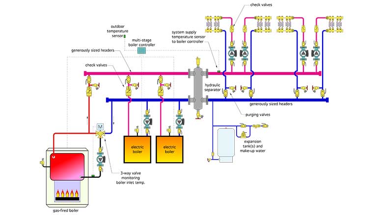
All three heat sources are piped in parallel and trimmed so that any one of them could potentially be removed for service if necessary, without affecting the operation of the remaining heat sources. Each boiler has its own circulator, which only runs when that boiler is active. Each boiler also has a check valve and purging valves.
The gas-fired boiler, which is now protected from low inlet water temperatures by a 3-way mixing valve that responds to boiler inlet temperature. When that temperature is less than 130° F, the cold port of the mixing valve is fully closed. This creates “recirculation” of water leaving the boiler directly back into the boiler. Very little heat is released to the headers. This action allows the boiler to quickly warm above conditions that cause sustained flue gas condensation.
All three heat sources connect through generously-sized headers to a hydraulic separator. In addition to isolating the pressure dynamics of the heat source circulators from those of the load circulator, the hydraulic separator provides efficient air and dirt separation for the system.
The water temperature on the load side outlet of the hydraulic separator is monitored by a 3-stage heat source controller, which operates all three heat sources based on its settings. Typically, it would use the gas-fired boiler as first-stage (assuming that the unit price of heat from gas is below that of electric resistance heating). The electric boilers would be operated as stage 2 and 3 in order to maintain a suitable supply water temperature to the load circuits. In most systems of this type, that supply water temperature would be based on outdoor reset control.
The 3-way mixing valves can be eliminated. They are not needed. All mixing occurs within the hydraulic separator. The multi-stage heat source controller provides all the necessary logic and heat source operation to achieve and maintain the necessary supply water temperature. This would significantly reduce cost and complexity.
Finally, each of the four zones is equipped with a check valve and purging valves.
Looking for a reprint of this article?
From high-res PDFs to custom plaques, order your copy today!


.jpg")