This website requires certain cookies to work and uses other cookies to help you have the best experience. By visiting this website, certain cookies have already been set, which you may delete and block. By closing this message or continuing to use our site, you agree to the use of cookies. Visit our updated privacy and cookie policy to learn more.
This Website Uses Cookies By closing this message or continuing to use our site, you agree to our cookie policy. Learn MoreThis website requires certain cookies to work and uses other cookies to help you have the best experience. By visiting this website, certain cookies have already been set, which you may delete and block. By closing this message or continuing to use our site, you agree to the use of cookies. Visit our updated privacy and cookie policy to learn more.
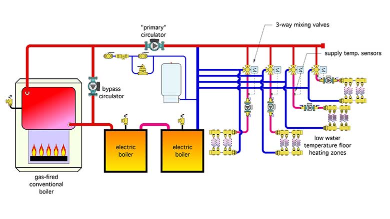
A recent inquiry involved a heating system for a school in which two electric boilers were being added to supplement the output of a gas-fired cast-iron boiler, and take advantage of low “off-peak” electrical rates. The load was four zones of low water temperature floor heating. The designer planned to operate the gas-fired boiler at temperatures high enough to avoid sustained flue gas condensation and to install a “bypass circulator” as another means of boosting boiler inlet temperature. A 3-way motorized mixing valve would be used to reduce the supply water temperature in each of the four zones. The proposed schematic for the modified system is represented (very closely) in Figure 1. Can you spot several details that would be better handled through an alternate design?