The Glitch + The Fix: Simpler and better
The Glitch:
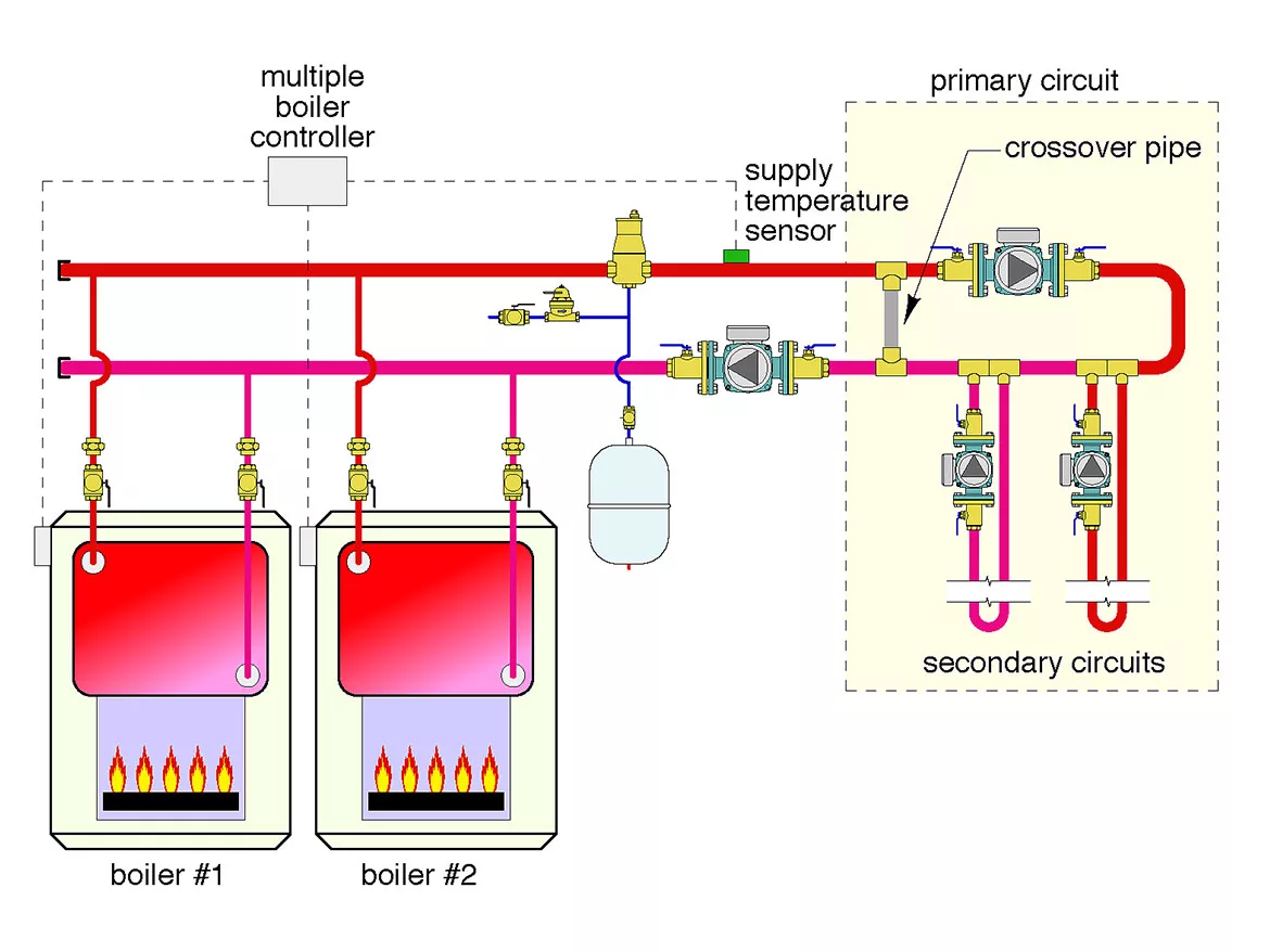
A multiple boiler system using sectional cast-iron boilers has been configured to supply two loads as shown below. A “crossover pipe” is installed in case the flow rate in the primary circuit is different from the flow through the boilers. There are several piping errors in this proposed design. Can you spot at least five of them?
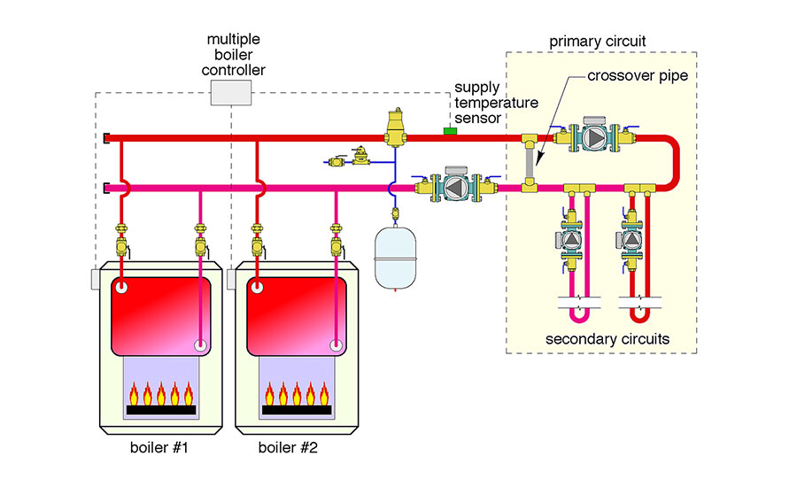 FIGURE 1 [click to enlarge]
The Fix:
The solution shown doesn’t require primary/secondary piping or closely spaced tees. It provides the same supply water temperature to each load circuit. This eliminates the temperature drop from one secondary circuit to the other, which would otherwise be present when a series primary loop is used. This arrangement also provides hydraulic separation of the load circulators based on a very low head loss through the hydraulic separator and “short/fat” headers. The hydraulic separator also provides air and dirt separation for the system, and thus eliminates the need for the air separator in the glitch drawing.
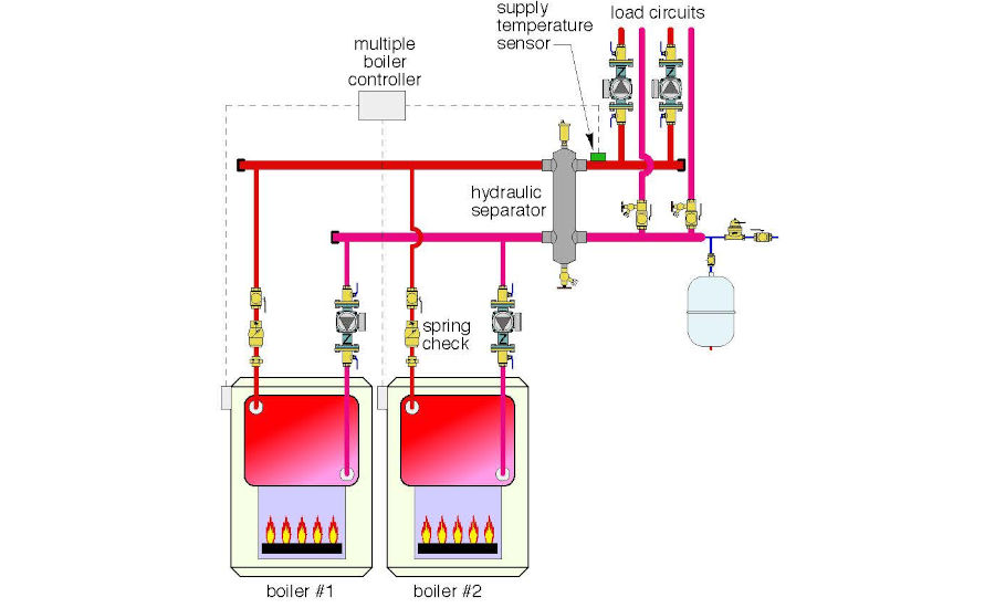 FIGURE 2 [click to enlarge]
Here’s a summary of the other corrections:
- Every boiler in a multiple boiler system should have its own circulator that only operates when that boiler is operating. The original schematic allows flow through all boilers regardless of which are firing. This results in needless heat loss from the boiler jacket and up the flues. Needless to say, most mechanical rooms do not need extra heat input when the boilers are operating.
- The unions and isolating ball valves that were installed with the intention of allowing each boiler to be isolated from the system and removed if necessary are not installed to make this is possible. It’s a seemingly small detail, but one you should always check.
- Always install the supply sensor for the boiler controller on the distribution system side of the hydraulic separation point. This is necessary because mixing can occur at the hydraulic separation point due to differences in the load flow rate compared to the boiler flow rate. Installing the temperature sensor downstream of this mixing point ensures that the final mixed supply water temperature will be detected by the boiler controller. That’s the temperature that boiler staging or modulation control should be based on.
- Every load circuit, whether it’s a secondary circuit as shown in the glitch drawing or a parallel circuit as shown in the fix drawing, should be equipped with a purging valve to allow efficient filling and flushing.
- When using primary secondary circuits (as was the intent in the glitch drawing), the secondary circulators should always pump into their respective circuits. This allows the primary loop to serve as the pressure reference point so the pressure within the secondary circuit increases when the circulator is on.
- In the glitch drawing the boiler circulator is pumping toward the point where the expansion tank connects to the system. There will be very little head loss through the sectional cast-iron boilers between this circulator and the expansion tank connection point. This will cause a drop in pressure upstream of the boiler circulator when it operates. Air could be sucked into the system through vents if the pressure at their location within the system goes sub-atmospheric.
Download The Glitch & The Fix: November 2021 PDF
Looking for a reprint of this article?
From high-res PDFs to custom plaques, order your copy today!


.jpg")
