The Glitch + The Fix: Swapping one “box” for another

The Glitch:
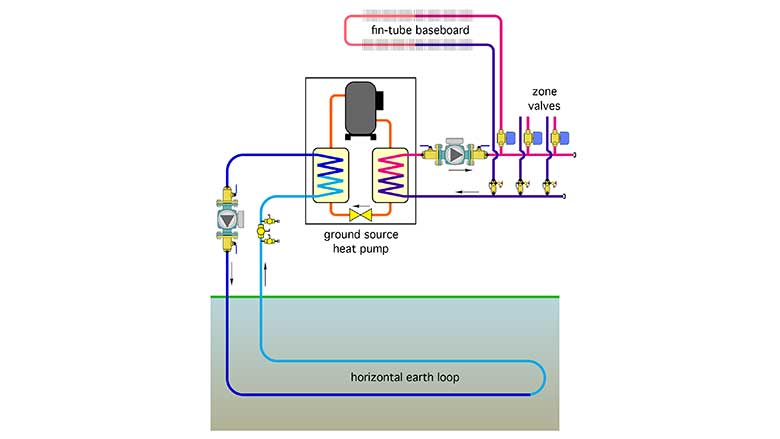
Given the current prices for fuel oil and propane, and current state and federal incentive programs, many homeowners are asking heating contractors to replace their aging boilers with a geothermal heat pump system. One installer, whose typical routine was to swap out an older boiler with a new boiler, with no consideration of the distribution system was asked to make the switch from an oil-fired boiler to a geothermal heat pump. The system he installed is shown in Figure 1. Use your knowledge of heat pump operating characteristics and basic hydronics to identify at least five design errors in this schematic.
The Fix:
The majority of current-generation water-to-water heat pumps are single-speed “on/off” devices. When on, they produce heat output at or near their rated output (depending on the exact entering temperatures and flow rates on both sides of the heat pump). There is very little thermal mass in a heat pump to store any heat that’s produced but not immediately sent to the load.
The distribution system shown in Figure 1 is zoned with valves, and thus, flow rates and rates of heat delivery can change drastically as the zones turn on and off. This will almost surely cause “out of range” operating conditions within the refrigeration circuit of the heat pump, leading to internal safety device trips (or worse).
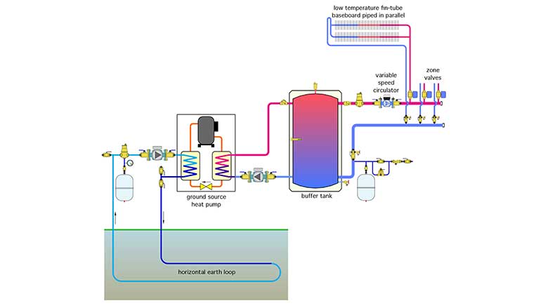
To prevent such conditions, it’s imperative to include a well-insulated buffer tank between the heat pump and the zoned distribution system as shown in Figure 2. The heat pump cycles on and off based on the setpoint temperature of the buffer tank and the temperature differential across which the tank needs to operate. The load circuits can now operate completely independently of the on/off cycling of the heat pump.
It’s also imperative that the heat emitters are compatible with the water temperatures available from the heat pump. I suggest that the entire distribution system should be designed (or in this case redesigned) so that it can deliver design heat output with a supply water temperature no higher than 120° F. In The Fix drawing, this is represented by a change to low-temperature baseboard piped in parallel. Other means of increasing the surface area of the heat emitters, and thus decreasing the required water temperature are certainly possible.
Other errors in the original design include:
- The lack of air separation on both sides of the heat pump;
- The lack of an expansion tank on both sides of the heat pump;
- Lack of differential pressure control on zoned distribution system;
- Failure to provide counter flow through the evaporator (earth loop) side of the heat pump; and
- Failure to route the coolest water (leaving heat pump evaporator) through the upper portion of the horizontal earth loop.
Details that correct these conditions are shown in the fix drawing.
Looking for a reprint of this article?
From high-res PDFs to custom plaques, order your copy today!


.jpg")