The Glitch + The Fix: Primary reduction

The Glitch:
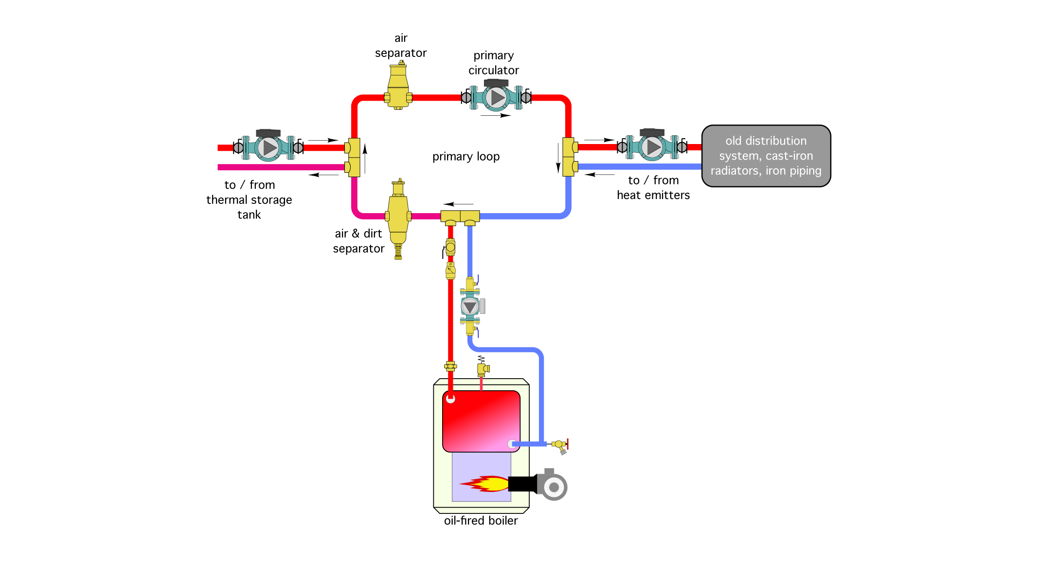
A heating pro is asked to retrofit a pellet-fired boiler to an existing distribution system consisting of older cast iron radiators, iron piping and an oil-fired boiler. The system needs to draw heat from a thermal storage tank heated by the pellet-fired boiler, as well as an existing oil fired boiler. The original heating distribution system was designed to use 180° F supply water on a design day, but will now be retrofitted by outdoor reset control. This will allow the distribution system to operate at supply water temperatures as low as 100° F on mild days. A portion of the proposed piping layout is shown below. Can you identify several details that could be improved?
The Fix:
Although the piping shown in the glitch drawing could work, it uses more hardware than necessary, and doesn’t place that hardware in optimal locations.
The objective of the system is to accept heat from the thermal storage tank and/or the auxiliary boiler, and send that heat to the distribution system. Although the primary/secondary arrangement could do this, it is not necessary. The primary loop and its associated circulator could be eliminated as shown Figure 2. This would reduce installation cost as well as operating cost over the life of the system.
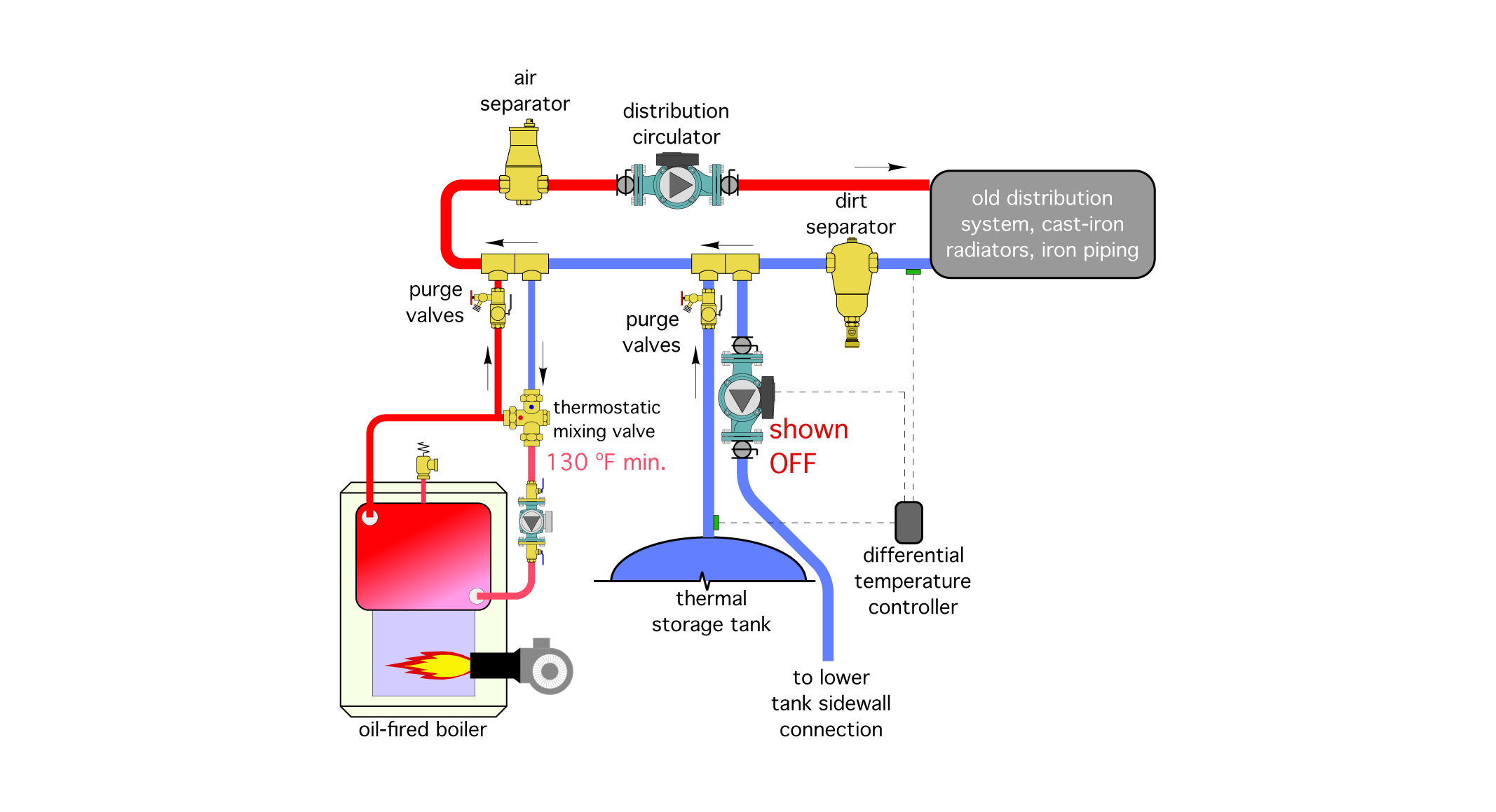
Each heat source (e.g., the thermal storage tank and the existing oil-fired boiler) connect to the distribution system using a pair of closely-spaced tees. This provides adequate hydraulic separation of all circulators.
Figure 2 is shown in a mode where the thermal storage tank is not contributing heat to the system. Perhaps the tank has been discharged to a low-temperature where it can no longer contribute heat to the system. Or, perhaps the pellet boiler is off-line for maintenance. In either case, the water temperature returning from the distribution system could be quite low (based on the use of outdoor reset control).
Although the oil-fired boiler in the original system did not operate with sustained flue gas condensation, that possibility now exists.
To prevent corrosion damage to the oil-fired boiler and its flue, a high flow capacity 3-way thermostatic mixing valve has been added to the oil-fired boiler. It will ensure that the water temperature entering this boiler is at or above 130° F whenever possible.
Other changes include moving the closely spaced tees that connect the thermal storage tank to the system “upstream” of those that connect the oil-fired boiler to the system. This allows the possibility of lower temperature heat being supplied from storage, while the oil-fired boiler operates to boost the water temperature as necessary.
If simultaneous operation of the thermal storage tank circulator and oil-fired boiler is allowed, the designer should also ensure that heat generated by the oil-fired boiler cannot be inadvertently transferred to the thermal storage tank. This is easily done by using a differential temperature controller to monitor the difference between the water temperature returning from the distribution system and the water temperature available from the top of the thermal storage tank. The latter is only allowed to contribute heat to the system if the tank temperature remains a few degrees above the return temperature from the distribution system.
Other modification include:
- Purging valves have been added to each secondary circuit; and
- The dirt separator has been moved to a location upstream of the heat sources.
In this position it is more likely to intercept and remove dirt returning from the old distribution system before it is carried into either heat source, or the other components in the reconfigured distribution system.
The makeover uses a controller that measures supply water temperature as well as outdoor temperature and the temperature of water entering the boiler. This allows for either outdoor reset or setpoint control of the supply water temperature. It also allows the controller to prevent sustained flue gas condensation in the boiler by limiting the rate of heat injection as the slab is warming up. The original approach using “on/off” injection mixing cannot provide boiler protection because it has no way to accurately vary how much hot water is leaving the boiler loop and flowing into the lower temperature portion of the system.
The on/off zone valve in the original system is also likely to be cycled several thousand times each heating season. It’s just a matter of time until it fails. It could be replaced, but the same high cycling frequency awaits the replacement.
Another somewhat “crude” aspect of the original system is the pressure drop imposed by the reduced piping size between points A and B is somewhat arbitrary. A globe valve is a much more precise way to induce the pressure differential needed to push flow through the motorized valve as it opens.
Notice that the boiler circulator in the original installation is pumping into the boiler and toward the expansion tank. This will cause a drop in system pressure around the boiler loop when the boiler circulator is on. The proper relationship between the boiler circulator and tee where the expansion tank connects is shown in Figure 2.
Figure 2 also adds a purging valve in the lower temperature loop, and an air separator.
Looking for a reprint of this article?
From high-res PDFs to custom plaques, order your copy today!


.jpg")