The Glitch & The Fix: Presumptuous primary piping

The Glitch:
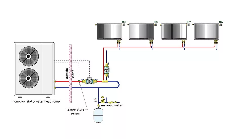
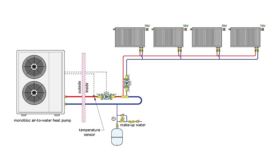
An installer plans to use a single-speed monobloc air-to-water heat pump to supply several panel radiators. The radiators are equipped with thermostatic radiator valves to allow for room-by-room zoning. Because of this, the install sets up the radiators in parallel and as a secondary circuit to the primary circuit running through the heat pump. The proposed piping layout is shown in Figure 1. The heat pump is enabled to operate whenever the outdoor temperature is at or below 55° F. The compressor and primary loop circulator run whenever the loop temperature drops to 120° or less, and turn off when the loop temperature reaches 130° or higher. Can you spot some potential problems with this layout? How would you propose correcting any issues you identify?
 The Fix:
When a single stage/low mass heat source (heat pump or otherwise) is connected to a extensively zoned distribution system, a buffer tank should be used to prevent short-cycling. There’s nothing about primary/secondary piping that precludes the need for a buffer. You have to have thermal mass.
Other problems:
- The panel radiators are piped in parallel direct return. Assuming they have approximately equal flow resistance, the radiator closest to the circulator will get the most flow. The radiators further out on the distribution mains will get progressively less and less flow. When parallel direct return piping systems are used, there should be a balancing valve on each radiator. That being said, some panel radiators have built-in balancing valves. In that case, the technical data for these valves (head loss versus flow rate) should be used to create approximately equal head loss though each piping path;
- Most manufacturers of monobloc-style air-to-water heat pumps want antifreeze in those heat pumps. Short of installing a heat exchanger between the heat pump and buffer tank, this implies the entire system needs to operate with an antifreeze solution. Putting an automatic make up water system on a system filled with antifreeze is very risky. If the pressure drops due to a minor but persistent leak, water will be added to replace the lost antifreeze. This could eventually dilute the solution to the point where it freezes;
- There is not pressure relief valve in the system of Figure 1;
- There is no means of differential pressure control, as the thermostatic valves on the radiators open and close;
- There is no central air separator in the system;
- The operating temperature range for the heat pump (on at 120° and off at 130°) is relatively high. The heat pump can likely provide these temperatures but the COPs are not going to be very good. More electrical energy used for a given amount of heat delivered; and
- Even if the primary/secondary piping was in order, the secondary circulator should be located to pump into the secondary circuit. There should also be a purging valve on the outlet side of the secondary circuit.
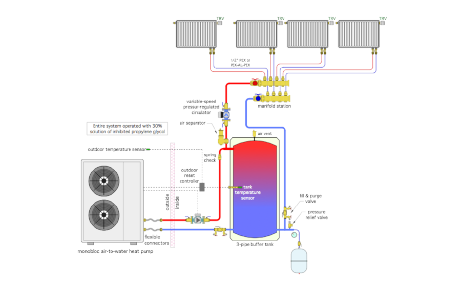
One configuration that corrects all these deficiencies is shown in Figure 2.
When the heat pump is enabled to operate (typically at beginning of heating season, and for the duration of that season), it monitors the temperature of the buffer tank sensor. The fixed temperature cycling range of 120° to 130°, although attainable, is relatively high for most air-to-water heat pumps.
Operating at those conditions will lower the heat pump’s COP. This has been changed in two ways.
First, the design load temperature swing of the buffer tank was changed to 110° to 120°. This may increase the required size of the panel radiators slightly, but it’s also going to improve the heat pump’s seasonal COP. Second, since this system only provides space heating, there is no need to maintain design load temperatures in the buffer tank under partial load conditions. An outdoor reset controller, rather than a setpoint controller will be used to determine the average tank temperature. At 50% of design load, the temperature swing of the tank will be 80° to 90°. The lower the tank temperature, the higher the heat pump’s COP. Some modern air-to-water heat pumps may have outdoor reset capability built in.
The panel radiators are set up as a homerun distribution system using 1/2-inch PEX or PEX-AL-PEX to supply each panel. While this configuration doesn’t guarantee that the right flow will “automatically” be established through each radiator, it does allow the balancing valves on each radiator — or on the manifold station — to be used to adjust the flows as necessary.
A variable-speed pressure-regulated circulator automatically changes speed to maintain an approximately constant differential pressure across the manifold station.
Filling and purging valves are provided. The expansion tank has been sized for the added volume of the buffer tank and the 30% solution of propylene glycol, which expands and contracts slightly more than water. No automatic make-up water system is needed. A pressure relief valve has also been added.
Download The Glitch and Fix: October 2020 in pdf form.
Looking for a reprint of this article?
From high-res PDFs to custom plaques, order your copy today!


.jpg")