The Glitch & The Fix: Seemingly simple

The Glitch:
A homeowner hires a heating contractor to upgrade his propane-fired cast-iron boiler to a mod/con boiler. The cast-iron boiler is only 15 years old and in good shape. The homeowner asks if the contractor can reuse it to add heat to his 18,000-gallon in-ground swimming pool. The installer knows that this is possible using a heat exchanger. The installer also knows that the relatively cool pool water could cause sustained flue gas condensation in the boiler, and therefore decides to use a “bypass loop” with a separate circulator as shown in Figure 1. Because the repurposed boiler will be located in the pool house, the entire system up to and including the primary side of the heat exchanger is filled with 50% propylene glycol antifreeze. Can you spot several details that will lead to problems in this layout?
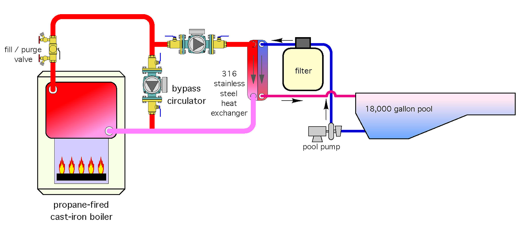 FIGURE 1 [click image to enlarge]
The Fix:
Whenever a conventional boiler (e.g, one that’s not intended to operate with sustained flue gas condensation) supplies a low temperature/high thermal mass load, that boiler needs “anti-condensation” detailing.
Although one might consider the brazed plate heat exchanger as having low thermal mass, it’s just interface for the thermal mass of 18,000 gallons of cold water in the pool. It’s there because chlorinated pool water would otherwise quickly corrode the cast-iron boiler.
A “bypass circulator” will not protect the boiler from sustained flue gas condensation. It has no way of “understanding” when the rate of heat transfer at the heat exchanger is greater than the rate of heat production at the boiler. Whenever the heat exchanger is transferring heat faster than the boiler is producing it, the fluid temperature between the two decreases. The larger the heat exchanger is, the more the fluid temperature will drop. It is very possible that the piping design shown in Figure 1 could keep the cast-iron boil in condensing mode whenever it operates, ultimately destroying the boiler and its venting system by corrosion.
The solution is a variable speed circulator operating in “setpoint” mode installed between the boiler loop and heat exchanger as shown in Figure 2.
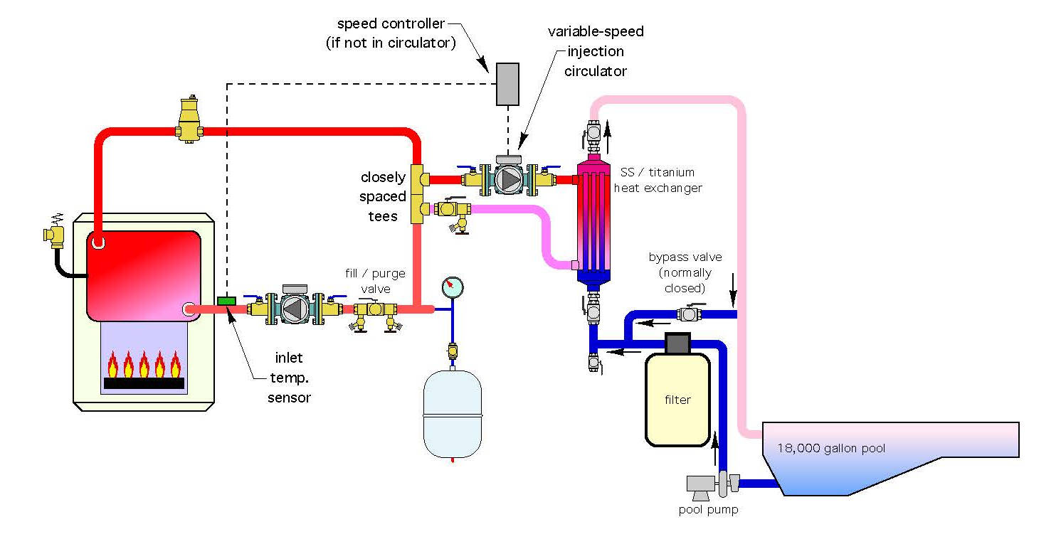 FIGURE 2 [click image to enlarge]
There are several circulators now available that have internal control logic for adjusting speed based on the temperature at an external sensor. It’s also possible to use an external temperature controller that can send a signal such as 2-10 VDC or 4-20 ma to a circulator with those control inputs.
For the system shown in Figure 2, the injection circulator would remain off until the boiler inlet temperature reached 130° F. It would then gradually speed up as the boiler inlet temperature continued to rise, reaching full speed when that temperature climbed to 135° or higher. This provides a “thermal clutch” between the boiler and load. It allows the full output of the boiler to reach the load, but doesn’t allow the load to extract heat faster than the boiler can produce it.
Other issues
There are several other details in Figure 1 that should be changed:
- Don’t assume that any stainless steel heat exchanger can be used with pool water. High concentrations of chlorine or other disinfectants can corrode 300-series stainless steel. Use a heat exchanger that’s specifically designed for pool heating. Some will use titanium, or alloys of stainless steel and titanium, for portions of the heat exchanger that contact pool water;
- The heat exchanger in Figure 1 is piped for co-current flow (e.g., both fluid streams passing through in the same direction). This is not optimal in terms of creating the highest possible temperature difference between the two fluids. To achieve the highest temperature difference the two fluids should pass through the heat exchanger in opposite directions. This is called “counter-current” flow. It’s how the heat exchanger in Figure 2 is configured;
- I also suggest installing a bypass pipe that could route pool water around the heat exchanger if ever necessary. Any isolation, drain, or bypass valves and fittings should be PVC, CPVC, or other materials specifically rated for use with pool water;
- The original layout lacks a pressure relief valve on the boiler, as well as an air separator and expansion tank. These have been added in Figure 2;
- Move the fill/purge valve so that it can also serve as a low point boiler drain; and
- Add a purge valve on the heat exchanger circuit to expedite air removal from the heat exchanger, and allow its primary side to be isolated if ever necessary.
Download December 2021 Glitch & Fix: Seemingly simple
Looking for a reprint of this article?
From high-res PDFs to custom plaques, order your copy today!


-glitch.webp?height=200&t=1644851746&width=200 "G&F February 2022 - Glitch")

.jpg")
