The Glitch & The Fix: Pellet particulars

The Glitch:
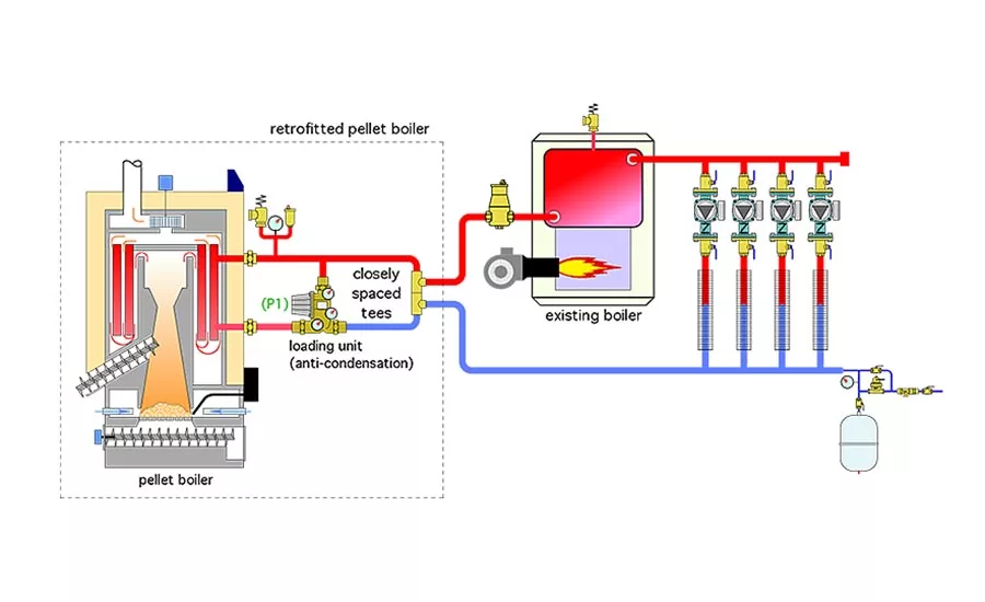
Figure 1 shows a piping layout that was used to retrofit a pellet-fired boiler to an existing 4-zone heating system supplied by an oil-fired boiler. The pellet boiler is protected against sustained flue gas condensation by a “loading unit,” which combines a circulator with a thermostatic mixing valve. The distribution system is connected to the retrofitted pellet boiler piping using a pair of closely spaced tees. Can you spot several errors in this piping layout and propose modifications that would correct them?

The Fix:
First and foremost: Pellet boilers need thermal storage. They are not designed to turn on and off multiple times each hour. Once started, pellet boilers should operate for multiple hours. A suggested average on-time is 3 hours per start. I’ve witnessed well-designed pellet boiler systems in which boiler had burn cycles lasting about 7 hours.
There are two reasons for this. One is to maximize the overall thermal efficiency of the boiler. The longer the burn cycle, the more time the boiler operates at or near steady state combustion conditions. The second reason — reduced emissions — follows as a result of the first.
The corrected system, shown in Figure 2, has a thermal storage tank with a minimum capacity of 2 gallons per 1,000 Btu/h of pellet boiler rating. It’s piped as a “3-pipe” configuration. This allows heat to go from the pellet boiler directly to the load when both are operating at the same time. It also helps preserve beneficial temperature stratification within the tank.
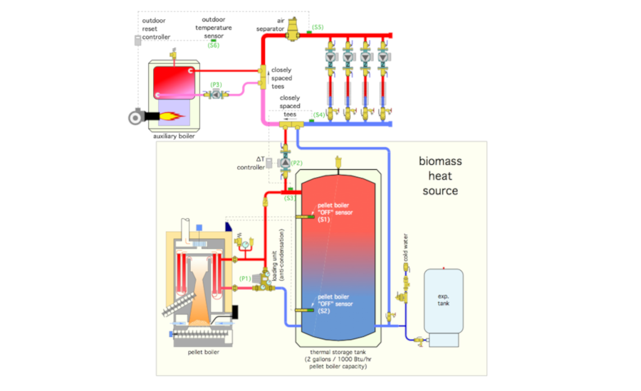
Think of the combination of the pellet boiler and thermal storage as the “biomass heat source.” Whenever possible, all heat needed by the loads will come from the biomass heat source. It’s injected into the distribution system at a pair of closely spaced tees. Likewise, any supplemental heat from the oil-fired boiler is injected into the distribution system at another set of closely-spaced tees. If either heat source is not operating, any flow in the distribution system passes straight through the set of tees associated with that heat source.
Other problems with the original layout include:
- The oil-fired boiler is piped in series with the distribution system. This was not a problem is when that boiler was the sole heat source. However, it becomes a problem when the biomass heat source is added. It allows water, heated by the biomass heat source, to flow through the oil-fired boiler when it’s off. This results in unnecessary heat loss from the unfired boiler into the mechanical room and up the flue. It also adds to head loss in the distribution system;
- The expansion tank in the original design is located very close to the discharge side of the zone circulators. Since the tank connection is the point of no pressure change when any of the zone circulators are operating, the dynamic pressure in the zone circuits will decrease when the zone circulators are on. This could allow air into the system. It also edges the zone circulators closer to potential cavitation depending on operating temperature and pressure;
- There are no purging valves at the return ends of the zone circuits; and
- The air separator should be downstream of all heat sources — where the water is hottest.
The system in Figure 2 includes several important details:
- The pellet boiler is turned on and off based solely on the temperatures in the thermal storage tank. When the temperature sensor in the upper portion of the tank drops to some preset value, the pellet boiler and loading unit are turned on. When the sensor in the lower portion of the tank reaches another preset (but significantly) higher temperature, the pellet boiler and loading unit are turned off. The operation of the pellet boiler and its loading unit are completely independent of any calls from thermostats associated with the loads;
- The injection circulator (P2) is only allowed to operate if the temperature at sensor (S3) is at least 5° F above the temperature returning from the distribution system at sensor (S4). This prevents heat, created by the oil-fired boiler, from being inadvertently sent into the thermal storage tank. This function is easily handled by a differential temperature controller; and
- The oil-fired boiler is turned on and off based on outdoor reset control. This ensures comfort will be maintained in the building even if the biomass heat source is unable to provide the minimum necessary water temperature. It also allows the temperature in the thermal storage tank to drop to the lowest possible value that can still maintain building comfort before firing the auxiliary boiler. This helps ensure long and efficiency pellet boiler cycles.
Download The Glitch and Fix: March 2021 in pdf form.
Looking for a reprint of this article?
From high-res PDFs to custom plaques, order your copy today!


.jpg")
