search
cart
facebook instagram twitter linkedin youtube
  • Sign In
  • Create Account
  • Sign Out
  • My Account
  • NEWS
  • PRODUCTS
    • FEATURED PRODUCTS
  • CONTRACTORS
    • BATH & KITCHEN PRO
    • BUSINESS MANAGEMENT
    • HIGH EFFICIENCY HOMES
    • TECHNOLOGY
    • WATER TREATMENT
    • PMC COLUMNS
      • Dave Yates: Contractor’s Corner
      • John Siegenthaler: Hydronics Workshop
      • Kenny Chapman: The Blue Collar Coach
      • Matt Michel: Service Plumbing Pros
      • Scott Secor: Heating Perceptions
  • ENGINEERS
    • CONTINUING EDUCATION
    • DECARBONIZATION | ELECTRIFICATION
    • FIRE PROTECTION
    • GEOTHERMAL | SOLAR THERMAL
    • PIPING | PLUMBING | PVF
    • PME COLUMNS
      • Christoph Lohr: Strategic Plumbing Insights
      • David Dexter: Plumbing Talking Points
      • James Dipping: Engineer Viewpoints
      • John Seigenthaler: Renewable Heating Design
      • Lowell Manalo: Plumbing Essentials
      • Misty Guard: Guard on Compliance
  • RADIANT & HYDRONICS
    • RADIANT COMFORT REPORT
    • THE GLITCH & THE FIX
  • INSIGHTS
    • CODES
    • GREEN PLUMBING & MECHANICAL
    • PROJECT PROFILES
    • COLUMNS
      • Codes Corner
      • Natalie Forster: Editorial Opinion
      • Guest Editorial
  • MEDIA
    • EBOOKS
    • PODCASTS
    • VIDEOS
    • WEBINARS
  • RESOURCES
    • INDUSTRY CALENDAR
    • DIRECTORIES
    • PM BOOKSTORE
    • CE CENTER
    • MARKET RESEARCH
    • CLASSIFIEDS
  • EMAGAZINE
    • EMAGAZINE
    • ARCHIVE ISSUES
    • CONTACT
    • ADVERTISE
    • PME EMAGAZINE ARCHIVES
  • SIGN UP!
Plumbing & Mechanical ContractorThe Glitch & The Fix

The Glitch & The Fix: Heat, heat everywhere

The Glitch
The Fix
The Glitch
The Fix
February 19, 2021

The Glitch:

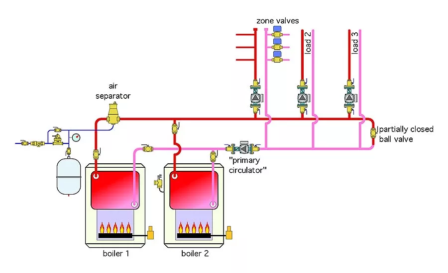
Figure 1 shows the piping layout for an actual installation. It uses two boilers, fired in stages, to supply three areas of a building. One of those areas is sub-divided into three zones. The other two areas are handled by individual zone circulators.  The “primary circulator” operates whenever any load circuit is on. All circulators are fixed speed, and there is a partially closed ball valve at the end of the “primary loop.”  

When any one of the three loads circuits is on, there is heat migration into the other two load circuits. The mechanical room where the boilers are located is also very warm, even when only one boiler is firing. Can you spot several errors in this piping layout and propose modifications that would correct them?

The Glitch

The Fix:

What’s wrong? In short, plenty.

This system is neither a primary/secondary nor a 2-pipe configuration. It’s an undefined morphing of the two. Because the “primary circulator” operates whenever any of the loads are on, it creates a pressure drop across the partially closed ball valve. The piping upstream of this valve is at a higher pressure than the piping downstream of the valve. This “∆P” induces a slow, but persistent flow through inactive zones, even when the circulators in those zone are off.

The system is also piped to allow flow through both boilers whenever one or more loads are active. When one boiler is on and the other is off, the flow of heated water through the unfired boiler creates heat loss through the boiler jacket and unnecessarily heats the mechanical room. This heat loss also slightly reduces the supply water temperature to the load circuits. The fix is to pipe each boiler with its own circulator which only operates when that boiler is operating. Also be sure to include two check valves (either integral to each boiler circulator, or as separate components). These checks prevent reverse flow through an inactive boiler when the other boiler circulator is on. 

Other missing or incorrect details include:

1. Placing the air separator when it only receives flow through Boiler 1;

2. Connecting the expansion tank close to the discharge side of the primary circulator (e.g., not pumping away);

3. Not having purging valves in each load circuit;

4. Lack of details to provide hydraulic separation of the circulators;

5. Having the inlet of the load circulators very close to the tees in the header (should always provide minimum of 12 pipe diameters of straight pipe upstream of circulator inlets);

6. No pressure relief valve on Boiler 1; and

7. No provision for draining either boiler if ever necessary.

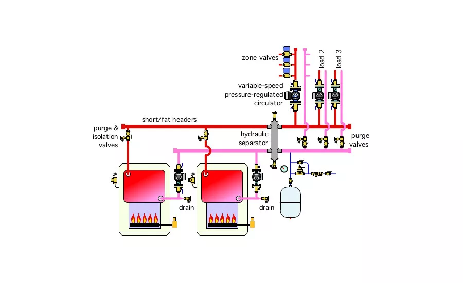
Figure 2 shows one way to correct these issues.  

The FixThis piping is based on a hydraulic separator between the heat production portion of the system and the loads. In addition to its primary role of hydraulic separation, this device also provides air and dirt separation. 

The use of “short and fat” headers also help ensure good hydraulic separation of all circulators. Flow to the loads supplied by the sub-circuits with zone valves is provided by a variable-speed pressure-regulated circulator. The zone valves have also be moved to the supply side of the sub circuits to help prevent thermal migration into circuit that are off. Purge valves have been added. 

The expansion tank connects near the hydraulic separator, which keeps the pressure within the later very stable regardless of which circulators are operating. The circulators for Load 2 and Load 3 both have internal check valves to prevent forward heat migration and prevent reverse flow. Both boilers have pressure relieve valves and drain valves.


Download The Glitch and Fix: February 2021 in pdf form.

KEYWORDS: boilers piping design plumbers and pipefitters troubleshooting

Share This Story

Looking for a reprint of this article?
From high-res PDFs to custom plaques, order your copy today!

Recommended Content

JOIN TODAY
to unlock your recommendations.

Already have an account? Sign In

  • 2025 Next Gen ALL-STARS hero 1440

    2025 Next Gen All Stars: Top 20 Under 40 Plumbing Professionals

    This year’s group of NextGen All-Stars is full of young...
    Plumbing & Mechanical Contractor
    By: Kristen R. Bayles
  • Worker using the Milwaukee Tool SWITCH PACK drain cleaner

    Pipeline profits: Drain cleaning, pipe inspection create opportunities

    Drain cleaning and inspection services offer lucrative...
    Green Plumbing and Mechanical
    By: Nicole Krawcke
  • Uponor employee, Arturo Moreno

    The reinvestment in American manufacturing and training

    Plumbing & Mechanical Chief Editor Nicole Krawcke and...
    Plumbing News
    By: Nicole Krawcke and Natalie Forster
Manage My Account
  • eNewsletters
  • Online Registration
  • Subscription Customer Service
  • eMagazine
  • Manage My Preferences

More Videos

Popular Stories

Hot water pipes

Campus shutdown at Oakland University exposes hidden risks of aging hot-water infrastructure

Floor heating manifold cabinet with flowmeter and PEX pipe.

Elegance extended: How to use the homerun system of connecting heat emitters

Industrial pressure gauge on a tank.

From cutting edge to classic: How to modernize outdated pneumatic control systems

Poll

Will business be up or down in 2025?

Do you anticipate business in 2025 to be up or down in comparison to 2024?
View Results Poll Archive

Products

The Water Came To A Stop

The Water Came To A Stop

See More Products
eBook | 2025 Radiant & Hydronics All Stars

Related Articles

  • Combining geothermal heat pumps and radiant

    The Glitch & The Fix: Combining geothermal heat pumps and radiant

    See More
  • Interior design, Product, Wood, Window, Door

    The Glitch + The Fix: Diagnosing an insufficient heat complaint

    See More
  • The Glitch

    The Glitch & The Fix: Presumptuous primary piping

    See More

Related Products

See More Products
  • 51EpbH0yOwL__SL210_.jpg

    We Got Steam Heat!

  • The ACCA Job Safety (1).jpg

    The ACCA On-The-Job Safety Handbook (Pack of 5)

  • what hydronics taught holohan.jpg

    What Hydronics Taught Holohan: A Memoir of Life in the Heating Industry

See More Products

Events

View AllSubmit An Event
  • August 26, 2014

    Free Webinar: Low Temperature Heat Emitter Options in Hydronic Systems

    With proper design, you can create systems that require supply water temperatures no higher than 120° F under design load conditions.
View AllSubmit An Event
×

Keep your content unclogged with our newsletters!

Stay in the know on the latest plumbing & piping industry trends.

JOIN TODAY!
  • RESOURCES
    • Advertise
    • Contact Us
    • Directories
    • Store
    • Want More
    • Supply House Times
  • SIGN UP TODAY
    • Create Account
    • eMagazine
    • eNewsletter
    • Customer Service
    • Manage Preferences
  • SERVICES
    • Marketing Services
    • Reprints
    • Market Research
    • List Rental
    • Survey/Respondent Access
  • STAY CONNECTED
    • LinkedIn
    • Facebook
    • Instagram
    • YouTube
    • X (Twitter)
  • PRIVACY
    • PRIVACY POLICY
    • TERMS & CONDITIONS
    • DO NOT SELL MY PERSONAL INFORMATION
    • PRIVACY REQUEST
    • ACCESSIBILITY

Copyright ©2025. All Rights Reserved BNP Media.

Design, CMS, Hosting & Web Development :: ePublishing