The Glitch & The Fix: Combining geothermal heat pumps and radiant
The Glitch:
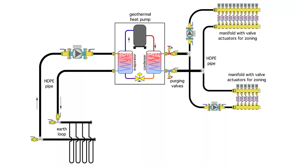
A contractor needs to combine a single-speed water-to-water geothermal heat pump to a highly zoned radiant floor heating system.
As a fallback for being short on inventory, his supply house buddy tells him that there’s no need for an expansion tank in the earth loop because the HDPE piping has enough “give” to accommodate any expansion or contraction. He now envisions the HDPE expanding and contracting like a piece of unreinforced rubber tubing, and assumes that he can use this to his advantage on the load side of the heat pump. He pipes up the radiant floor manifold with leftover pieces of HDPE pipe as shown in Figure 1. He uses two fixed-speed circulators, one to supply each manifold station. Individual circuit zoning at each manifold station is done using manifold valve actuators, each wired to a thermostat.
Can you identify several problems with this approach and propose a better one?
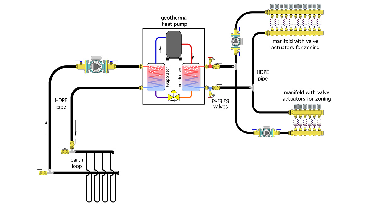 FIGURE 1 - Click to enlarge image
The Fix:
Although HDPE pipe does expand and contract as it changes temperature, it does so at a different rate compared to that of the glycol solution it contains. This difference in expansion rates can cause wide pressure fluctuations in earth loop.
Using an expansion tank in the earth loop portion of the system — as he originally planned — is a far better approach. It can greatly reduce the variations in earth loop pressure between summer and winter operating conditions. Since the earth loop is just another type of closed loop assembly it should also be equipped with an air separator.
Take a close look at how the earth loop circuits are headed in Figure 1. They’re connected in a direct return configuration. This will cause unequal flow rates in the different parallel circuits. When the goal is to keep individual branch circuits that have about the same flow resistance, operating at about the same flow rate, those circuits should be in a reverse return configuration, as shown in Figure 2.
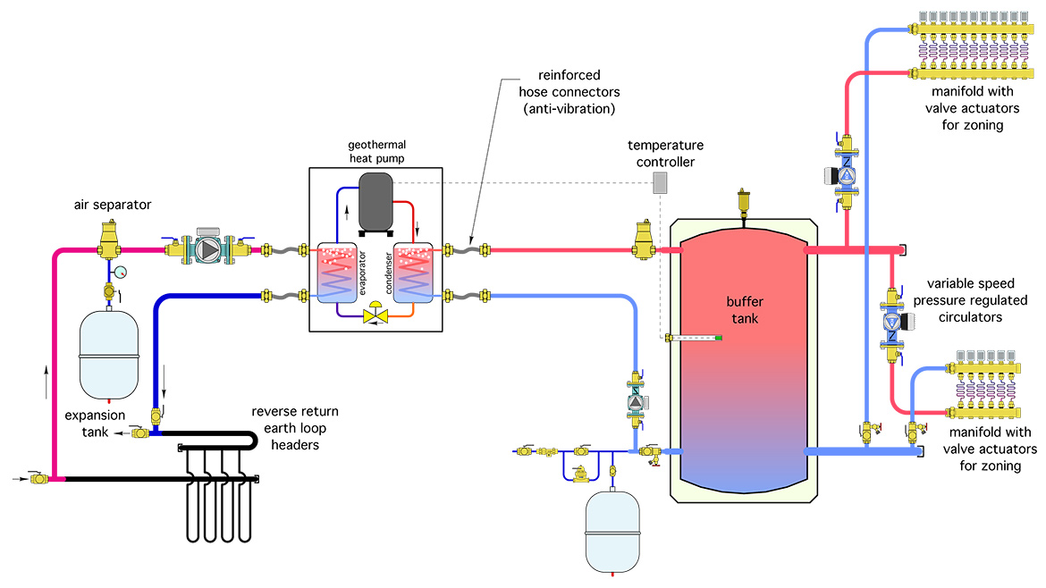 FIGURE 2 - Click to enlarge image
The load side of the system shown in Figure 1 also has several shortcomings:
- The upper manifold is piped so entering flow goes downward through the manifold valves. This will likely cause flow noise and potential water hammer as the valve discs move close to their seats.
- A zoned distribution system supplied by an on/off heat pump needs a buffer tank. The tank allows the rate of heat input from the heat pump to be very different from the rate of heat delivery to the distribution system. Without the buffer tank, the heat pump will short cycle and possibly even trip off on its internal high head pressure switch when only a small load is present. The buffer tank shown in Figure 2 also serves as a hydraulic separator between the heat pump circulator and distribution circulators. This is especially relevant since there are now variable speed circulators, operating in constant differential pressure mode, on the load side of the system.
- There must be a properly sized expansion tank on the load side of the heat pump. In this case, it is mounted near one of the lower connections to the buffer tank. Mounting it on either side of the buffer tank is acceptable.
- The valves shown just to the right of the heat pump are intended to be used for purging the distribution system. As shown, they would only be able to purge the load side of the heat pump. Figure 2 shows properly placed and oriented purge valves on the outlet side of each branch circuit.
- Finally, both water-to-water and air-to-water heat pumps should connect to adjacent piping using anti-vibration hose connectors. This helps reduce vibration transmission from the heat pump to rigid piping.
The makeover uses a controller that measures supply water temperature as well as outdoor temperature and the temperature of water entering the boiler. This allows for either outdoor reset or setpoint control of the supply water temperature. It also allows the controller to prevent sustained flue gas condensation in the boiler by limiting the rate of heat injection as the slab is warming up. The original approach using “on/off” injection mixing cannot provide boiler protection because it has no way to accurately vary how much hot water is leaving the boiler loop and flowing into the lower temperature portion of the system.
The on/off zone valve in the original system is also likely to be cycled several thousand times each heating season. It’s just a matter of time until it fails. It could be replaced, but the same high cycling frequency awaits the replacement.
Another somewhat “crude” aspect of the original system is the pressure drop imposed by the reduced piping size between points A and B is somewhat arbitrary. A globe valve is a much more precise way to induce the pressure differential needed to push flow through the motorized valve as it opens.
Notice that the boiler circulator in the original installation is pumping into the boiler and toward the expansion tank. This will cause a drop in system pressure around the boiler loop when the boiler circulator is on. The proper relationship between the boiler circulator and tee where the expansion tank connects is shown in Figure 2.
Figure 2 also adds a purging valve in the lower temperature loop, and an air separator.
Looking for a reprint of this article?
From high-res PDFs to custom plaques, order your copy today!


