The Glitch + The Fix: Diagnosing an insufficient heat complaint
The Glitch:
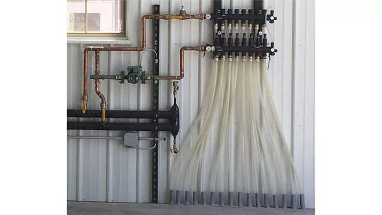
Figure 1 is photo sent to me for a “diagnosis.” It shows part of a floor heating system in a commercial building located in a cold climate. The manifold station serves eight circuits of 5/8” PEX tubing. The copper piping supplying the manifold station is 3/4” size. Water temperature to the supply manifold is regulated by a thermostatic mixing valve. There’s a flo-check valve at the top of the copper piping assembly. Flow appears to be created by a small zone circulator. The insulated horizontal piping makes a “U-turn” just to the left of the risers from the floor circuits.
FIGURE 1
Figure 2 is a schematic for what I believe to be the piping and hardware in this photo.
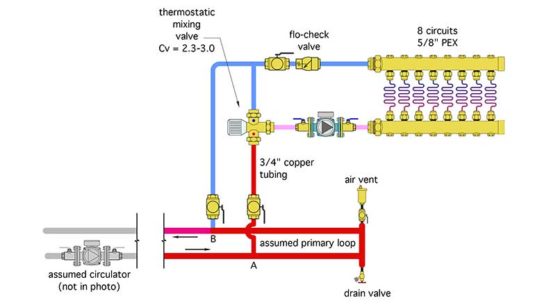
FIGURE 2
Imagine that you, an independent heating pro, have been asked to inspect this system because the owner is claiming it doesn’t deliver sufficient heat on cold days. You’ve already checked out the boiler and near boiler piping, and determined that it was done correctly, and is not the source of the complaint.
The problems:
Because the system uses 5/8” PEX tubing, the designer must have been looking to operate the circuits with flow rates in access of 1 gpm. The 5/8” PEX tubing can carry 1.7 gpm with a flow velocity of 2 feet per second, and about 3.3 gpm at a flow velocity of 4 feet per second. To be conservative, let’s assume the lower flow rate of 1.7 gpm in each of the eight circuits. That would make the total manifold flow rate 13.6 gpm.
The 3/4” copper tubing should be limited to a flow rate of 6.5 gpm if the flow velocity is not to exceed 4 feet per second. Thus, the copper tubing is definitely undersized for the (assumed) flow requirement.
Another likely issue is the Cv rating of the thermostatic mixing valve. Judging by its appearance, this valve, which is intended for use in domestic water systems, likely has a Cv between 2.3 and 3.0. The Cv value is the flow rate, in gallons per minute that would create a 1 psi pressure drop. Pressure drop increases with the square of flow rate. Thus, IF the flow through the valve could even get to 8 gpm, the pressure drop, just through the mixing valve, would be about 7.1 psi. That pressure drop would add to the pressure drop through the copper tubing and the floor heating circuits. The circulator shown in the photo could not generate 8 gpm at 7.1 psi (16.4 ft of head), much less the added head loss of the piping. The bottom line: That mixing valve is a severe flow bottleneck in this portion of the system. The fix would be a valve with a significantly higher Cv (in the range of 12-15).
There will also be a pressure drop in what I assume is a primary piping circuit between points A and B. That pressure drop will create some heat migration into the remaining piping assembly whenever the primary circulator is on. This condition may be “tolerable,” but it’s not ideal.
The Fixes:
Figure 3 shows one way to revise the piping while keeping the same general layout (e.g., a primary loop supplying heat to this manifold station and other sub-assemblies).
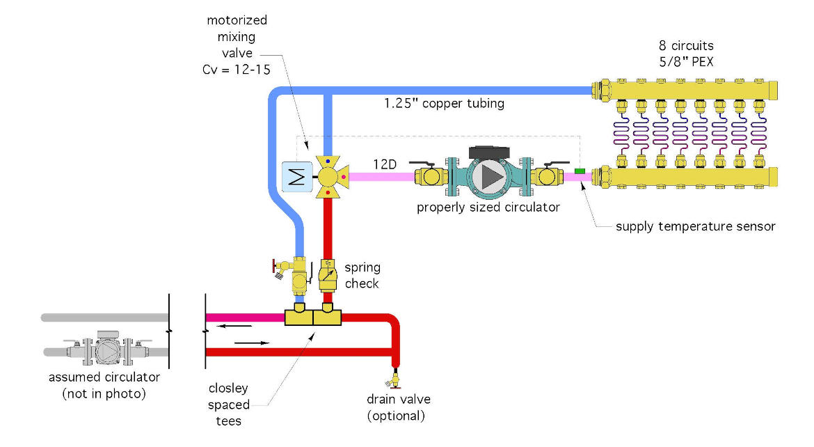
FIGURE 3
The portion of the system supplied by this assembly has been converted to a true secondary circuit (of an overall primary / secondary system). The closely spaced tees prevent the pressure dynamics present in the primary loop from influencing flow in this secondary loop.
The mixing valve has been changed to a motorized device with a Cv rating of at least 12 to perhaps 15. This eliminates the flow bottleneck present with the low Cv thermostatic mixing valve.
The circulator has been properly sized to provide at least 13 gpm to the manifold station.
The flo-check (or spring check) has been moved to where it can prevent heat migration into the secondary circuit when that circuit is inactive.
The tubing supplying the manifold station has been upsized to 1.25”.
A purging valve has been added to the return side of the secondary circuit just above the closely speed tees.
The float vent at the end of the primary loop is not necessarily causing problems, but it’s unnecessary and has been eliminated. The drain valve is also “optional,” so it was left in place.
There is at least 12 pipe diameters of straight pipe length on the inlet side of the circulator.
Looking for a reprint of this article?
From high-res PDFs to custom plaques, order your copy today!


.jpg")
