The Glitch & The Fix: Inadvertent flows

The Glitch:
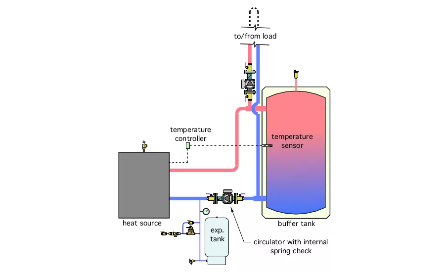
An installer recently read about the benefits of piping a buffer tank in a “2-pipe” configuration. One benefit was “direct to load” heat transfer when the load and heat source are operation simultaneously. Another benefit, under the same operating conditions, was enhanced stratification within the tank due to reduced flow rate into and out of the buffer tank. The piping used by the installer is shown in Figure 1.
Once the system was in operation, the owner contacted the installer complaining that the heat source was “hot” even when it was not operating. The installer returned to the site and confirmed this was indeed occurring. While there, the installer also noticed the water temperature supplied to the load was a few degrees cooler than the water temperature in the upper portion of the tank. This temperature drop seemed unlikely due to heat lost over a very short amount of pipe.
Can you figure out what’s happening to cause these issues? Can you develop some modifications to eliminate these issues?

The Fix:
“2-pipe” buffer tanks do provide the benefits referenced above. They also have an “Achilles heel” that needs attention if the benefits are to be realized. The underlying problem is the original design lacks a sufficient means of preventing some of the flow returning from the load from passing through the heat source when it’s not running. Even though the head loss associated with the piping path through the heat source is greater than that through the buffer tank, it’s not zero. The flow returning will divide up at the lower tee, the majority of this flow will pass through the tank. The rest will pass through the heat source. The latter flow will dissipate heat through the heat source and its piping. That’s why the heat source feels hot even when it’s not running. This “cooled” flow will then recombine with hot water from the buffer tank and thus dilute the water temperature supplied to the load.
Ah, but isn’t there a spring check valve in the heat source circulator to prevent all this? Yes, that check valve is there, but it has a relatively low forward opening resistance of perhaps 0.3 to 0.5 psi. This is usually insufficient to prevent the undesired flow through the inactive heat source, especially if the piping path through the buffer tank has higher than necessary flow resistance due to several feet of piping, or several fittings.
A modified piping diagram is shown in Figure 2.
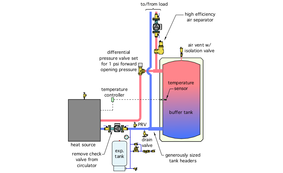
Here’s a summary of the changes and improvements:
1. A differential pressure valve, set for 1 to 1.5 psi, provides sufficient forward opening resistance to prevent undesirable flow through the heat source when it’s off. This valve also prevents reverse thermosiphoning between the tank and heat source when the heat source circulator is off. It can also be completely closed to isolate the heat source in combination with the isolation flanges on the heat source circulator.
2. The piping leading to the heat emitters is connected as close as possible to the tank. This, in combination with short and generously sized headers at the tank, keep the head loss through the tank as low as possible, and thus encourage flow returning from the load to pass through the tank rather than “attempt” to flow through the heat source piping.
3. The expansion tank is connected on the inlet side of the heat source circulator.
4. A central air separator has been included in the piping leading to the load to ensure good separation of microbubbles at a location where the water is at a relatively high temperature.
5. A drain valve has been added to allow the tank to be drained if necessary.
6. A small ball valve has been installed under the float vent at the top of the buffer tank to allow the latter to be isolated and serviced if necessary.
7. The check valve has been removed from the heat source circulator to ensure that any pressure increase can “communicate” with the expansion tank.
Download The Glitch and Fix: January 2021 in pdf form.
Looking for a reprint of this article?
From high-res PDFs to custom plaques, order your copy today!


.jpg")
