The Glitch and Fix: Dampened response

The Glitch:
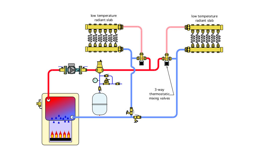
An installer is asked to pipe two independent zones of high mass floor heating to a conventional gas-fired boiler. The layout he chooses is shown in Figure 1. Two 1-inch pipe size thermostatic mixing valves are used to provide two different supply temperature settings. Each manifold station is expected to operate at 10 gallons per minute of flow.
Can you spot several errors in this layout? Can you come up with an improvement? By the way, I’ve left you a hint at the boiler.
The Fixes:
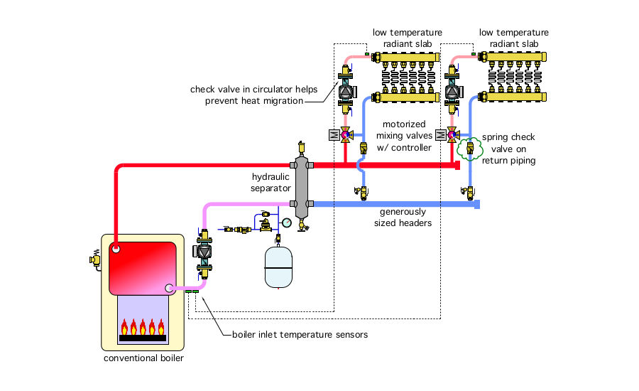
Several errors are present in the original drawing. They are listed below. Figure 2 shows one way to correct all of them.
-
There will be very little (and very inadequate) flow through the radiant panel circuits because there are no circulators between the mixing valves and their respective manifold stations. The revised schematic shows a separate circulator for each zone. Those circulators are placed between the mixing valve and manifold station.
-
There is no detail to protect the conventional boiler against sustained flue gas condensation. See point 6 below for how this has been corrected.
-
The circulator shown is placed upstream of the point where the expansion tank connects to the system. Circulators should always pump away from the point where the expansion tank connects to the system, and there should be low flow resistance between this point and the inlet of the circulator. This is accomplished by a generously sized header in the revised schematic.
-
There is no backflow preventer in the make-up water system. This is a violation of most mechanical/plumbing codes. The revised schematic has a backflow preventer in the make-up water system.
-
The purging valves are installed backward. The revised schematic corrects this detail.
-
Just because the thermostatic mixing valves have 1-inch piping connections doesn’t mean they are adequate for several gallons per minute of water flow. Most small thermostatic mixing valves — up to 1-inch pipe size — are intended for use as tempering devices in domestic hot water systems. They typically have low Cv ratings and thus create very high flow resistance when used in hydronic heating systems where several gallons per minute of flow are expected. This problem and the lack of flue gas condensation protection described in No. 2 above, has been corrected by using motorized mixing valves operated by electronic controllers that sense and react to boiler inlet temperature to prevent sustained flue gas condensation.
-
There are no check valves to prevent flow reversal through one of the zones when it is off and the other zone is on. Check valves have been added to the revised schematic..
Please read here to view The Glitch and Fix: October 2019 in pdf form.
Looking for a reprint of this article?
From high-res PDFs to custom plaques, order your copy today!


