The Glitch and Fix: How hard can it be?
The Glitch:
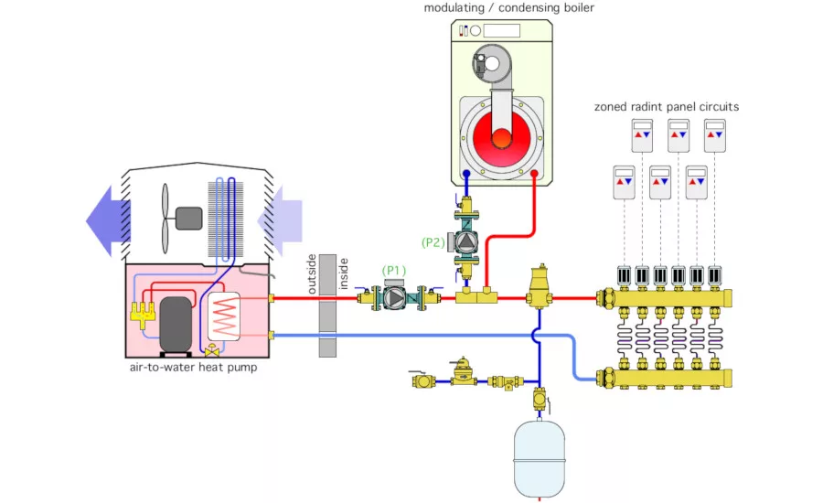
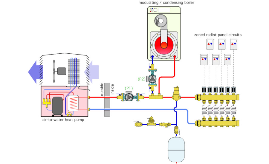
An installer was asked to include an air-to-water heat pump into a low-temperature radiant panel heating system supplied by a mod/con boiler. The owner planned to use the heat pump as the sole heat source during shoulder seasons when its COP would be high, as well as during times when off-peak electrical rates were available. The boiler would be the heat source if the heat pump was down for service or during extremely cold weather (-5° F or lower).
The installer extended the distribution system outside as shown in Figure 1. He rationalized this as a way to prevent freezing within the heat pump since some heat from the remainder of the system would be flowing through the heat pump whenever circulator (P1) was operating, and thus there would be no need for antifreeze. Can you spot a few details that are going to cause problems and propose alternative approaches?
> Figure 1
The Fix:
There are several problems with this layout.
-
The concept of maintaining continuous flow through the heat pump to prevent freezing fails if no zone is calling for heat or if a prolonged power outage occurs. It’s also likely that a substantial amount of energy will be associated with operating the heat pump’s circulator (typically 1/12 HP) as well as the cost of scavenged heat from the indoor portion of the system.
-
Circulator (P1) is pumping toward the location where the expansion tank connects to the system. This will lower the pressure within the radiant panel circuits when that circulator is operating and potentially lead to circulator cavitation or air being sucked into the system at any minor leakage points.
-
There is very little thermal mass in this system to stabilize either heat source if only one or two zones are operating. A buffer tank is needed when low mass heat sources are connected to an extensively zoned distribution system.
-
There is no provision to isolate either heat source from the balance of the system if necessary for service.
-
The backflow preventer on the makeup water system is downstream of the pressure reducing valve. The order of these two components should be reversed (e.g., backflow preventer upstream of the pressure reducing valve).
-
The inlet of the boiler circulator is very close to the side port of one tee in the closely spaced pair. This tends to increase turbulence entering the circulator increasing operating noise. There should be at least 10 diameters of straight pipe upstream of any circulator.
-
There is no pressure relief valve in the system.
One way to correct for these deficiencies is shown in Figure 2.
> Figure 2
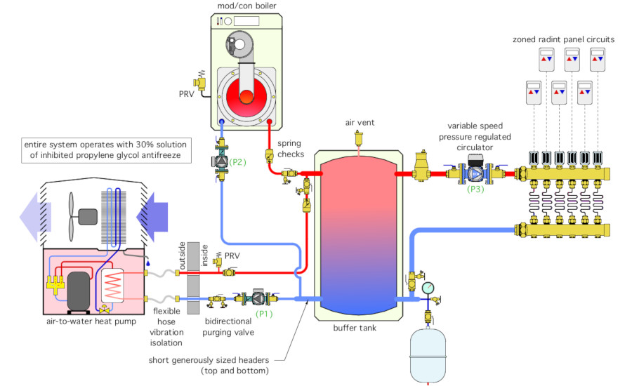
Both heat sources are piped in parallel to the buffer tank. Depending on the control strategy, either heat source could operate independently, or they could operate simultaneously if needed. Either heat source can be isolated if necessary. Because they are combined at the short generously sized tank headers, the buffer tank provide hydraulic separation of circulators (P1) and (P2). Circulator (P3) is a variable speed circulator that’s set for constant differential pressure. Its speed automatically ramps up and down as the manifold valve actuators open and close based on zone demand. This circulator is also hydraulically separated from the other circulators by the buffer tank. Each heat source has a pressure relief valve that would not be isolated from that heat source if the isolation valves for the heat source are closed. The two spring-load check valves prevent reverse circulation through either heat source and stop reverse thermosiphoning from the tank through either heat source. The entire system operates with an antifreeze solution sufficient to prevent freezing of the heat pump during a prolonged power outage in cold weather.
Please read here to view The Glitch and Fix: April 2019 in pdf form.
Looking for a reprint of this article?
From high-res PDFs to custom plaques, order your copy today!