The Glitch: Pipe it just like any other boiler

The Glitch:
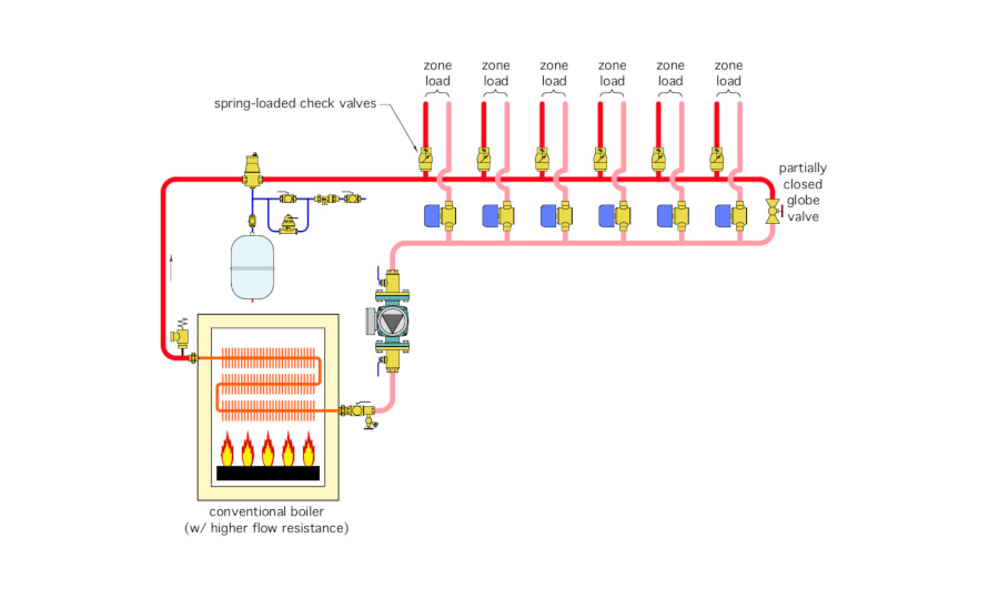
An installer sets up a zoned distribution system as shown below. To keep it simple, he uses the same size piping for the headers and all the distribution circuits. The heat source is a low-mass, copper-tube boiler with high-flow resistance. The distribution system operates at water temperatures high enough that sustained flue gas condensation will not occur.
To prevent heat migration, he installs a spring-loaded check valve at the beginning of each zone circuit, just above the header. To control differential pressure, he installs a partially open globe valve across the ends of the headers. He sets the globe valve for one-turn open.
Can you identify and describe at least six details that should be changed?
The Fix:
Here’s what’s wrong and how to correct it:
-
The high-flow resistance boiler will create significant variation in zone flow rates depending on which zones are open. The boiler’s low thermal mass heat exchanger can create noises under low flow conditions when only one or two zones are operating.
-
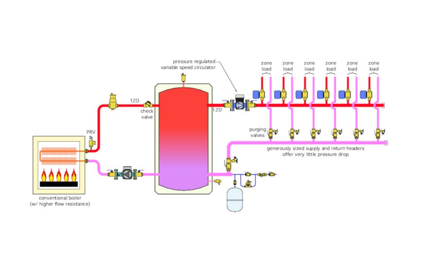
The partially closed ball valve is a poor excuse for proper differential pressure control across the headers. A variable speed, pressure-regulated circulator is now the state-of-the-art method for providing such control in systems using valve-based zoning.
-
Headers should always be generously sized to minimize pressure drop along their length. This helps minimize flow rate variations as different zones turn on and off. I suggest headers be sized for a flow velocity not to exceed 2 feet per second under full design flow rate.
-
Any “flow sensitive” boiler supplying a system using zone valves should be decoupled from the distribution system through some means of hydraulic separation. In the fix drawing this is accomplished with a buffer tank, which also adds thermal mass to prevent boiler short cycling.
-
It’s never a good idea to install check valves near fittings that create high turbulence. This is the case with the check valves shown on the supply side of zone in the glitch drawing. There should always be at least 12 diameters of straight piping upstream of any check valve to calm turbulence that otherwise can cause the disc side of the check valve to rattle. However, heat migration in this, the fix drawing, is eliminated by simply installing the zone valves on the supply side of the zone circuits. Do this and there’s no need for check valves on each zone circuit.
-
Purging valves on each zone circuit are missing in the glitch drawing. They are shown in the fix.
-
The circulator location in the glitch drawing, in combination with the likely pressure losses of the piping system, puts the circulator in a “pumping toward” rather than “pumping away” situation with respect to the expansion tank. Installing the expansion tank near the lower inlet of the buffer tank keeps the point of no pressure change close to the inlet of both circulators.
Please read here to view The Glitch and Fix: March 2019 in pdf form.
Looking for a reprint of this article?
From high-res PDFs to custom plaques, order your copy today!


