The Glitch and Fix: I'll do it anyway
The Glitch and Fix: January 2019
The Glitch: I'll do it anyway
An installer is asked to install heating in the slab floor of a farm workshop. The owner has already purchased a used cast iron boiler that will run on propane. The installer isn’t too happy about this because he had planned on using a wall hung mod/con boiler. Still, he agrees to do the installation.
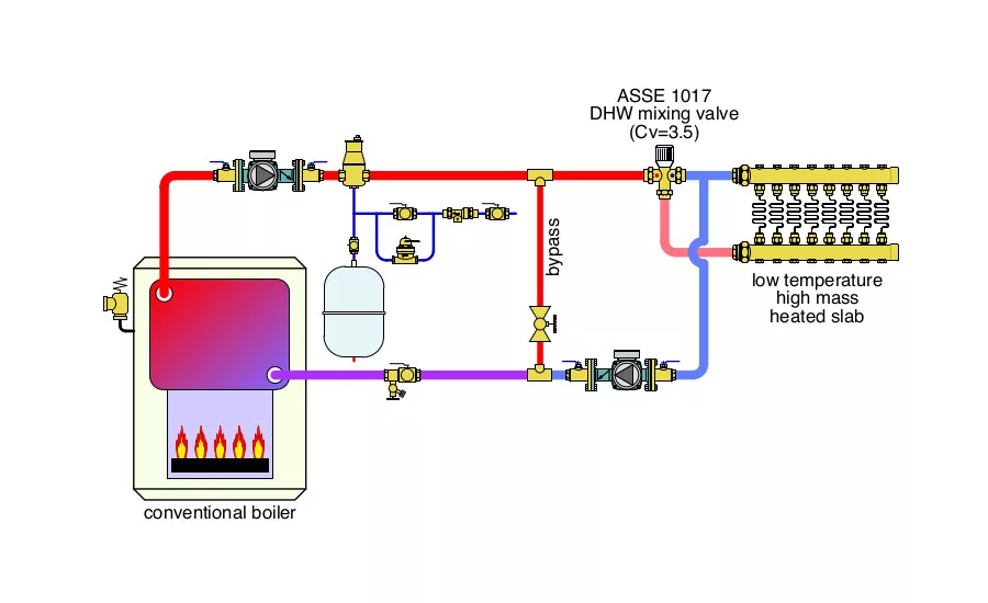
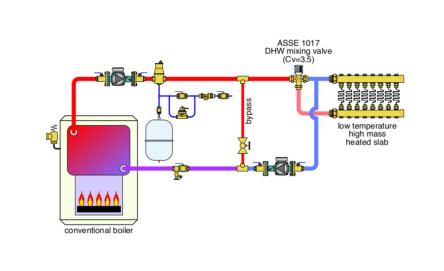
He sets up the piping shown below with a bypass pipe to boost boiler inlet temperature. He also selects a 1” pipe size ASSE 1017 mixing valve with a Cv of 3.5 to reduce the water temperature to the floor circuit. He chooses a standard 1/25 hp circulator for the radiant floor manifold subsystem.
Can you find at least four errors in this installation, and propose a better way to do this system using the same cast-iron boiler?
The Fix: There are several problems with this proposed installation.
-
A bypass pipe will not protect the boiler from sustained flue gas condensation because it can’t sense and react to boiler inlet temperature. See this month’s Hydronics Workshop column for more information.
-
There will be very little flow through the radiant floor circuits due to the placement of the circulator. Instead of moving adequate flow through these circuits the circulator will pull flow from the hot port to the cool port of the mixing valve. Remember: When flow is pushed out of a circulator all it “cares about” is getting back to the inlet port, and will take the easiest path to do so. There may still be a trickle of heated water flowing through the floor circuits, but definitely not enough to heat the building properly.
-
The ASSE 1017 mixing valve is designed for tempering domestic hot water. Even thought its pipe size matches the floor heating manifold, its Cv of 3.5 is much too low for this application. Assuming a desired flow rate of 1.0 gpm through each of the 8 floor heating circuits. This valve would create a head loss of about 12 feet. That’s more than the 1/25 hp circulator could create, even at zero flow rate!
-
The boiler circulator is “pumping toward” the expansion tank. It should be “pumping away” from the point where the expansion tank connects to the system.
-
The purge valve near the boiler inlet is installed backward.
-
There is no effective hydraulic separation between the circulators. Flow rates will be unpredictable.
The improved design is shown above. 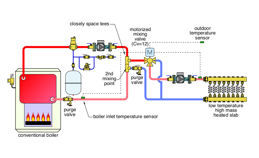
This design uses a motorized three-way mixing valve with an integral controller/actuator that monitors boiler inlet temperature, supply water temperature, and outdoor temperature. The latter is used for outdoor reset control. This valve has a Cv of 12, allowing it to pass plenty of flow to the radiant floor circuits with a head loss of less than 2 feet. The controller operating the valve’s actuator will throttle back hot water flow into the valve when necessary to keep the boiler inlet temperature above the dew point of the exhaust gases. The closely spaced tees provide hydraulic separation of the circulators, and the second mixing point needed to boost boiler inlet temperature.
The boiler circulator now pumps away from the expansion tank’s connection point. The purging valves are installed in the correct locations and orientations.
Please read here to view The Glitch and Fix: January 2019 in pdf form.
Looking for a reprint of this article?
From high-res PDFs to custom plaques, order your copy today!


