Out of touch

The Glitch
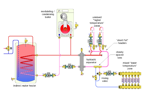
Eager to keep up with this new technology, an installer decides to install a hydraulic separator between a boiler and distribution system as shown to the right. The space-heating loads consist of two “unmixed” zone circuits and one mixed zone circuit. The installer connects the unmixed higher-temperature loads upstream of the mixed lower-temperature load. All the load circuits are supposed to operate independently. The indirect water heater is operated as a priority load.
When the system was turned on, there was very little warmth from the low-temperature loads. What’s the problem? Can you also spot a few more missing or incorrect details?

The Fix
A hydraulic separator eliminates the need to use closely spaced tees when connecting load circuits. All load circuits can be piped across the headers. Those headers should be short and generously sized. This keeps the pressure drop along the length of the header extremely small (e.g., negligible). The slow flow rate along the vertical height of the hydraulic separator adds virtually nothing to this pressure drop.
Thus, the differential pressure between the upper and lower headers is essentially zero. Each load connected across the headers is unable to detect the presence of the other load circuits.
Using closely spaced tees downstream of the hydraulic separator adds a second unnecessary and undesirable hydraulic separation between the lower-temperature “mixed” circuit and the hydraulic separator. The lower circuit will only receive heated water when the circuits connected across the header are active. At other times the water returning to the lower header will simply make a U-turn and be drawn back into the hot port of the mixing valve.
The solution is simple: Pipe all the loads across the headers as shown in the Fix drawing.
Other errors in the original system, that have been corrected in the Fix drawing, include:
- Lack of an expansion tank and makeup water assembly.
- Upside-down purging valve in the wrong location on the lower-temperature circuit.
- Lack of some strategically placed purging valves.
- Adding a properly placed check valve on the return side of the lower temperature load, since that load is now connected across the headers.
- Adding another check valve on upper coil inlet of indirect tank to minimize thermosyphoning along the upper pipe.
Links
Looking for a reprint of this article?
From high-res PDFs to custom plaques, order your copy today!


