Renewable Heating Design | John Siegenthaler
An Open & Shut Case (Part 1)
From heat exchanger selection to piping strategies, understanding thermal storage design is key to maximizing hydronic system performance.
.webp?t=1782963661)
The future of electric utilities will be heavily influenced by energy storage. Some will be in the form of large battery arrays capable of storing megawatt•hours of electrical energy. Some will involve privately owned batteries controlled as demand response resources by the utility. And some will be from pumped storage combined with hydro-electric generation (e.g., pumping water back up into a reservoir during low demand periods so that it can flow through turbines during subsequent high demand periods).
Storage allows utilities to partially level the daily demand profile. Electricity generated during periods of low demand can be temporarily “parked” in storage. That energy can subsequently be released to limit the need to operate expensive “peaking plants” when demand is high. Storage is also critically important in managing intermittent renewable generation from large solar and wind power plants.
Although there’s a lot of interest in battery-based systems, energy storage is not limited to electricity. There are applications where thermal energy storage has a decided advantage over batteries in terms of life cycle cost, safety, and resource efficiency.
A Huge Opportunity
Water is the best stuff on earth for storing sensible heat (e.g., where the material storing the heat changes temperature but not phase). On a volume basis, water can store more than twice the amount of heat compared to concrete, where both materials undergo the same temperature change. Hydronics technology is the ideal way to store and transport thermal energy. There is virtually no limit to the types of systems that combine a heat source, a volume of water to store that heat, and a means of delivering that heat precisely when and where it’s needed within a building.
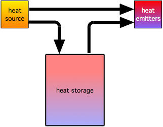
In its most basic form, a hydronic system with energy storage requires a minimum of three operating modes:
- The heat source adds heat to storage
- The storage supplies heat to the load
- The heat source supplies heat directly to the load.
These modes are illustrated in figure 1.
In hydronic based systems, the heat source could be an electric boiler, and air-to-water heat pump, or a geothermal water-to-water heat pump.
The heat emitters could be almost anything that can deliver the required rate of heat delivery based on the temperature cycling range of the storage system. Lower temperature emitters such as certain types of radiant panels, generously sized panel radiators, and fan-coils allow a greater temperature cycling range of the thermal storage system. Their lower operating temperature also improves the seasonal COPs of heat pumps used as the heat sources.
The thermal storage system could be one or more insulated tanks filled with water. It could also be one or more thermal storage devices that use a phase-change material. In this column I want to focus on water-based thermal storage, and more specifically, non-pressurized thermal storage tanks.
Non-pressurized thermal storage tanks have advantages and limitations relative to pressurized tanks. One advantage is that non-pressurized tanks over 119 gallons do not require ASME certification, as do pressure-rated tanks. Other advantages include:
- Lower cost per gallon of storage relative to steel and especially ASME certified tanks.
- Supplied with higher R-value insulation
- Modular construction allowing installation of large tanks in spaces accessed through typical passage doors.
Now some downsides:
- Non-pressure tanks must be vented to the atmosphere (to avoid any possibility of pressure build up). There will be some water loss due to evaporation over time, and thus the water level needs to be monitored, and make-up water periodically added to maintain necessary fill level.
- Because they are “open” to atmospheric pressure, the water in the tank will absorb some oxygen. To avoid oxidation, all piping components that handle water from the tank must be made of metals such as brass, bronze, stainless steel, or suitable engineered polymers. Stainless steel circulators are widely available, but often cost two to three times more than cast iron circulators of similar capacity.
- Depending on temperature and the surrounding environment, it is possible for certain aerobic microbes to establish themselves within biofilms in open systems. This can be dealt with using biocides.
- The water level in the tank is always at atmospheric pressure (e.g., 0 gauge pressure). Any piping that’s directly connected to the water in the tank and installed above the water level will be under sub-atmospheric pressure when circulators are off. Depending on the height of the piping above the water level and the temperature, it is possible for the water to reach its vapor pressure and boil when the circulator shuts off. Even in lower temperature systems where boiling can’t occur, air can be pulled into the system through devices such as air vents or loose valve stem packings in piping above the water level. This can cause the water to “settle” back toward the tank when the circulator is off. When the circulator turns back on it may or may not be able to re-prime the circuit. Even when the circulator can re-prime the circuit, there will be noise as air is pushed along the piping and eventually back to the tank.
Thermal Coupling
When non-pressurized tanks are used for thermal storage, they are typically coupled to the balance of system using a heat exchanger. This allows the balance of system to be operated as a closed loop.
The “traditional" type of heat exchanger in such an application is a helical coil of copper or stainless steel tubing immersed in the tank water. Although simple in concept, helical coil heat exchangers are limited in thermal performance by natural convection on the outer surface of the coil. Convection coefficients on this outer surface can be less than 10% of those associated with forced convection on the inner coil surface. About the only way to compensate for this heat transfer “bottleneck” is to increase coil surface area, by installing large coils or multiple coils that are headered together in parallel. Given the current cost of copper, this can get very expensive (think several thousands of dollars) for a coil array capable of transferring 50,000 Btu/hr with a 5 ºF approach temperature difference.
The alternative is a brazed plate stainless steel heat exchanger. These heat exchangers operate with pumped fluid streams on both side and thus at much higher convection coefficients. They are readily available from several sources, and typically sized using software provided by the manufacture.
The Ins and Outs
Regardless of the physical configuration of the heat exchanger, it’s import that it operates with counterflow conditions (e.g., the two fluids move in opposite directions through, or across the heat exchanger). This yields the highest log mean temperature difference (LMTD) between the two fluids, and thus the highest possible heat transfer rate for a given set of operating conditions.
Piping a heat exchanger for counterflow is relatively simple in most applications where the heat exchanger is moving heat in one direction (from a higher temperature fluid to a low temperature fluid). However, when the heat exchanger is used for heat input and heat extraction from thermal storage, the direction of flow needs to change to maintain beneficial temperature stratification within the thermal storage tank and counterflow on both sides of the heat exchanger.
One concept is to use two circulators, pumping in opposite directions, and where only one circulator operates at a given time. This is shown in figure 2.
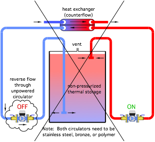 Image courtesy of John Siegenthaler. The unknown here is that flow needs to pass backward through the circulator that’s off. This is “uncharted waters” as far as circulator manufacturers are concerned.
 Engineer to manufacturer: “Would sending flow backward through an unpowered circulator create any problems?”
Manufacturer’s response: “Don’t know. Why would you want to do that anyway?”
My take is that reverse flow through an unpowered circulator should be avoided. In addition to an unknown head loss factor, reverse flow through an unpowered circulator is likely to spin the impeller backward. While this may or may not be a problem electrically for induction or PSC motors, it’s likely to generate a voltage within an ECM circulator (e.g., spinning a permanent magnet rotor within surrounding stator coils, is essentially a generator).
The work around is to combine a motorized valve with each circulator that serves as a bypass when the circulator is off. Each circulator also requires a check valve (internal or external). Figure 3 shows the concept.
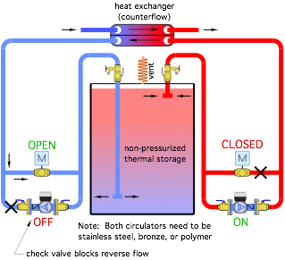 Image courtesy of John Siegenthaler. Trimming It Out
There are several other details shown in figure 2 that you might be wondering about.
- Question: Why is the circulator so low in the diagram?
- Answer: To maximize the static water pressure and net positive suction head at the circulator inlet and avoid cavitation.
- Question: Why are there two purging valves at the top of the thermal storage tank?
- Answer: They are used to fill the “goose neck” piping that goes over the top of the tank with water and flood the circulator inlet piping.
- Question: What’s the small coil labelled “vent” at the top of the tank?
- Answer: It’s a coil of small diameter copper tubing that helps condense water vapor rising from the tank causing it to flow back into the tank. This reduces evaporative water loss over time.
- Question: What are the red and blue tees at the ends of the pipes within the tank?
- Answer: They direct flow horizontally rather than vertically to minimize disruption of temperature stratification within the tank.
- Question: Why is there a note stating that the circulators need to be stainless steel, bronze, or polymer?
- Answer: These circulators are part of an “open” system. Cast-iron circulators will eventually corrode due to the presence of dissolved oxygen in the water.
More to Come
Next month, the “reversible” thermal storage system shown in figure 2 will be combined with a heat source and load. We’ll also get into how each of the operating modes shown in figure 1 are facilitated.
Looking for a reprint of this article?
From high-res PDFs to custom plaques, order your copy today!


