Smart Balancing - Part 1
An introduction to
pressure-independent balancing valves.

Attaining proper flow rates through all parallel branches of a hydronic distribution system is a vital part of delivering the expected comfort. The usual intent of balancing is for the installer, or perhaps a separate testing-and-balancing contractor, to adjust several manually set balancing valves so that the flow rates in each branch of the system are at, or very close to, a listing of flow rates prescribed by the system designer. When these design flows are achieved, the system is considered to be properly balanced.
There are surely thousands of hydronic heating and cooling systems installed with manually set balancing valves. In most cases these are globe-type valves with precision shafts for precise movement of the plug relative to the seat. The shape of the plug in these valves is likely to give them an “equal percentage” characteristic.
 A valve with an equal
percentage characteristic allows flow to increase very slowly when the valve’s
plug first starts to lift above its seat. The farther the plug lifts, the
faster the space through which flow can pass increases. Figure 1
shows a sequence in which the plug of an equal percentage valve moves
progressively upward away from its seat.
A valve with an equal
percentage characteristic allows flow to increase very slowly when the valve’s
plug first starts to lift above its seat. The farther the plug lifts, the
faster the space through which flow can pass increases. Figure 1
shows a sequence in which the plug of an equal percentage valve moves
progressively upward away from its seat.
Valves with equal percentage character-istics allow the relationship between the valve’s shaft movement and the heat output of the terminal unit through which it regulates flow to be approximately proportional. Thus, opening the valve’s shaft 50 percent of its total travel will yield approximately 50 percent heat output from the terminal unit, relative to its full heat output when the balancing valve is fully open.

A relatively new type of hydronic balancing valve has been developed to mitigate this undesirable effect. It is called a pressure-independent balancing valve (PIBV). These valves are configured to maintain a preset flow rate over a wide range of differential pressure. They rely on an internal compensating mechanism to adjust a specially tapered flow orifice within the valve so that a calibrated flow rate is maintained, typically within a tolerance of +/- 5 percent of the flow rating.
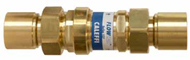
 PIBVs are available in different body designs. Some have a simple
cylindrical body such as shown in Figure 1, while others combine
pressure-testing ports and an isolating ball valve along with the internal
compensating mechanism. That mechanism is known as the valve’s “cartridge.” It
consists of a cylinder, a spring-loaded piston, and a combination of fixed- and
variable-shape orifices through which flow passes.
PIBVs are available in different body designs. Some have a simple
cylindrical body such as shown in Figure 1, while others combine
pressure-testing ports and an isolating ball valve along with the internal
compensating mechanism. That mechanism is known as the valve’s “cartridge.” It
consists of a cylinder, a spring-loaded piston, and a combination of fixed- and
variable-shape orifices through which flow passes.
This cartridge gives a PIBV the ability to maintain a relatively stable flow rate over a wide range of differential pressure. Figure 3 shows a cut-away view of the valve in Figure 2 showing the internal cartridge assembly.
Each cartridge used in a PIBV is manufactured to maintain a specific flow rate. Manufacturers can change the internal cartridge within a given body to produce a range of various (fixed) flow rates (e.g., 2.0 gpm, 3.0 gpm, etc).
At low differential pressures (2 to 5 psi, depending on the specific valve make and model), the internal compensating mechanism of the cartridge does not move. This allows the maximum free-flow area through the valve. Flow passes through both the fixed- and variable-shaped orifices. However, at such low differential pressures, the cartridge cannot adjust to maintain fixed flow rates. Thus, flow rate through the valve increases if differential pressure across the valve increases. The “inactive” position of the internal cartridge is shown in Figure 4. Notice that the internal spring is fully extended.
 If the differential
pressure across the PIBV exceeds the minimum threshold pressure of the valve,
thrust against the internal piston assembly begins to move it in the direction
of flow. The spring is partially compressed by this action. Under this
condition, the piston partially obstructs the tapered slot through which flow
must pass. However, the flow passage is now automatically
adjusted so that the valve maintains its calibrated flow rate at the
higher differential pressure.
If the differential
pressure across the PIBV exceeds the minimum threshold pressure of the valve,
thrust against the internal piston assembly begins to move it in the direction
of flow. The spring is partially compressed by this action. Under this
condition, the piston partially obstructs the tapered slot through which flow
must pass. However, the flow passage is now automatically
adjusted so that the valve maintains its calibrated flow rate at the
higher differential pressure.
This ability of the cartridge to hold its calibrated flow rate remains in effect until the differential pressure across the valve exceeds an upper threshold limit of 14 to 35 psi (depending on valve make and model). Such high differential pressure is relatively uncommon in most well-designed hydronic systems that include some means of differential pressure control.
If the differential pressure across the valve does exceed the upper pressure threshold, the piston and counterbalancing spring can no longer maintain the calibrated flow rate. The piston’s position completely blocks flow through the tapered orifice. All flow must now pass through the fixed orifice. This condition is shown in Figure 5. The result will be an increase in flow rate if differential pressure increases above the upper pressure threshold.

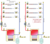 When a PIBV is installed in each branch of a system, the flows through
each active branch remain at its design value, regardless of the flow in other
branches. This is shown in Figure 7.
When a PIBV is installed in each branch of a system, the flows through
each active branch remain at its design value, regardless of the flow in other
branches. This is shown in Figure 7.
However, this desirable condition is contingent upon keeping the differential pressure across the PIBV between its lower and upper threshold values. This condition is vitally important to proper application of such valves, and will be discussed in next month’s Hydronics Workshop column.
Figure 1. Opening sequence for a globe valve with equal percentage plug.
Attaining proper flow rates through all parallel branches of a hydronic distribution system is a vital part of delivering the expected comfort. The usual intent of balancing is for the installer, or perhaps a separate testing-and-balancing contractor, to adjust several manually set balancing valves so that the flow rates in each branch of the system are at, or very close to, a listing of flow rates prescribed by the system designer. When these design flows are achieved, the system is considered to be properly balanced.
There are surely thousands of hydronic heating and cooling systems installed with manually set balancing valves. In most cases these are globe-type valves with precision shafts for precise movement of the plug relative to the seat. The shape of the plug in these valves is likely to give them an “equal percentage” characteristic.
Figure 2. Example of a small cylindrical PIBV.
Valves with equal percentage character-istics allow the relationship between the valve’s shaft movement and the heat output of the terminal unit through which it regulates flow to be approximately proportional. Thus, opening the valve’s shaft 50 percent of its total travel will yield approximately 50 percent heat output from the terminal unit, relative to its full heat output when the balancing valve is fully open.
Figure 3. PIBV body contains a spring-loaded cartridge assembly that is
designed to maintain a specific fixed flow rate over a wide range of
differential pressure.
This changes everything
One nuance of manually set balancing valves, whether they are equal percentage or otherwise, is that a change in the flow rate in any branch of a multibranch system causes the flow rates in other branches to change. This happens because the differential pressure across the branches that remain open changes whenever another branch opens or closes.A relatively new type of hydronic balancing valve has been developed to mitigate this undesirable effect. It is called a pressure-independent balancing valve (PIBV). These valves are configured to maintain a preset flow rate over a wide range of differential pressure. They rely on an internal compensating mechanism to adjust a specially tapered flow orifice within the valve so that a calibrated flow rate is maintained, typically within a tolerance of +/- 5 percent of the flow rating.
Figure 4. Under very low differential pressure, the spring does not
compress and the cartridge cannot maintain a fixed flow rate.
This cartridge gives a PIBV the ability to maintain a relatively stable flow rate over a wide range of differential pressure. Figure 3 shows a cut-away view of the valve in Figure 2 showing the internal cartridge assembly.
Each cartridge used in a PIBV is manufactured to maintain a specific flow rate. Manufacturers can change the internal cartridge within a given body to produce a range of various (fixed) flow rates (e.g., 2.0 gpm, 3.0 gpm, etc).
At low differential pressures (2 to 5 psi, depending on the specific valve make and model), the internal compensating mechanism of the cartridge does not move. This allows the maximum free-flow area through the valve. Flow passes through both the fixed- and variable-shaped orifices. However, at such low differential pressures, the cartridge cannot adjust to maintain fixed flow rates. Thus, flow rate through the valve increases if differential pressure across the valve increases. The “inactive” position of the internal cartridge is shown in Figure 4. Notice that the internal spring is fully extended.
Figure 5. When the differential pressure across the valve reaches a
specific value, the piston has moved as far as it can. At or above this
differential pressure the PIBV cannot maintain its calibrated flow rate.
This ability of the cartridge to hold its calibrated flow rate remains in effect until the differential pressure across the valve exceeds an upper threshold limit of 14 to 35 psi (depending on valve make and model). Such high differential pressure is relatively uncommon in most well-designed hydronic systems that include some means of differential pressure control.
If the differential pressure across the valve does exceed the upper pressure threshold, the piston and counterbalancing spring can no longer maintain the calibrated flow rate. The piston’s position completely blocks flow through the tapered orifice. All flow must now pass through the fixed orifice. This condition is shown in Figure 5. The result will be an increase in flow rate if differential pressure increases above the upper pressure threshold.
Figure 6. Differential pressure vs. flow rate curve for a PIBV.
Stay on the line
The flow rate vs. differential pressure characteristics of a given PIBV is shown in Figure 6. The desirable condition is to maintain the differential pressure across the valve between the lower and upper threshold values. For the valve represented in Figure 6, this would be between 2 and 32 psi as represented by the green vertical line. Operation in this differential pressure range allows the internal cartridge to remain active so that the valve can maintain its calibrated flow rate.Figure 7. With PIBVs installed, the flow rate in each branch holds constant when other branches open or close.
However, this desirable condition is contingent upon keeping the differential pressure across the PIBV between its lower and upper threshold values. This condition is vitally important to proper application of such valves, and will be discussed in next month’s Hydronics Workshop column.
Links
Looking for a reprint of this article?
From high-res PDFs to custom plaques, order your copy today!


.jpg")