Smart Balancing - Part 2
The proper application of pressure-independent balancing valves.

The pressure-independent balancing valves discussed in July’s Hydronics Workshop column make it easy to achieve and maintain fixed flow rates within each crossover and branch of a system. When properly applied, PIBVs also minimize variations in flow rates as zone valves or thermostatic radiator valves begin closing within the system.
Last month, I described how PIBVs use a specially shaped, spring-loaded cartridge to maintain their factory-set flow rate over a wide range of differential pressure. Most currently available PIBVs can maintain their factory-set flow rate within a relatively narrow tolerance (+/- 5 percent) provided that the differential pressure across them remains between a specific minimum and maximum value.
This characteristic is depicted by the green line in Figure 1, where a valve with a minimum differential pressure of 2 psi and a maximum differential pressure of 32 psi is assumed. These minimum and maximum differential pressure thresholds vary with the manufacturer, type and size of the PIBV.
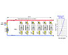
Consider the situation shown in Figure 2. It consists of six parallel branches, each with a terminal unit, zone valve and a PIBV. The latter have been selected for the different design flow rates required for each crossover.

If the terminal units are similar or identical, and thus all operate at approximately the same flow rate, it is likely the flow path through the crossover farthest from the circulator will have the highest hydraulic resistance.
If the terminal units are significantly different and operate at significantly different flow rates, the flow path of greatest hydraulic resistance must be identified by calculating the head loss along the flow path through each crossover at its design flow rate, and comparing the results to find the path with the highest total head loss.
 Once the path of
highest total head loss is identified, the circulator
should be sized to provide the design flow rate when all zones are open, with a
head equal to the head loss of the most restrictive flow path. The latter must include
the head loss of the supply and return mains, the branch piping, terminal unit
and the minimum operating differential pressure of the
PIBV.
Once the path of
highest total head loss is identified, the circulator
should be sized to provide the design flow rate when all zones are open, with a
head equal to the head loss of the most restrictive flow path. The latter must include
the head loss of the supply and return mains, the branch piping, terminal unit
and the minimum operating differential pressure of the
PIBV.
The calculation for head loss will typically require the head loss of each segment of the supply and return mains, out to and back from the most restrictive crossover, to be individually calculated and then added together. Yes, this takes some time, but it’s an essential part of properly applying PIBVs.
This head loss also could be estimated by assuming a typical main’s piping sizing criteria of 3 to 5 feet of head loss per 100 feet of pipe. The latter is a common rule of thumb used by some engineers. For example: Assume the piping mains in the system shown in Figure 3 have been sized for a head loss of 5 feet per 100 feet of pipe. Also assume that all terminal units and associated branch piping are identical and require 4 gpm each while operating. The minimum operating pressure differential of the PIBV is 2 psi. The system operates with water at an average temperature of 140 degrees F.
Based on this description and these assumptions, determine the minimum circulator flow/head requirement for this system.
 The total
head loss of the flow path through the most remote heat emitter is the head
loss of the mains, plus the head loss of the heat emitter and branch piping, plus
the minimum operating head loss of the PIBV. These can
be determined separately and then added.
The total
head loss of the flow path through the most remote heat emitter is the head
loss of the mains, plus the head loss of the heat emitter and branch piping, plus
the minimum operating head loss of the PIBV. These can
be determined separately and then added.
The graph on the right side of Figure 3 shows that each heat emitter creates 6 feet of head loss at the desired operating flow rate of 4 gpm.
The total estimated head loss of the supply and return piping mains, out to and back from the farthest branch is:
 The minimum required head loss of the PIBV needs to be calculated from
its minimum required pressure drop. This requires the density of water at an
average temperature of 140 degrees F, which is 61.3 lb/ft3. The head
loss across the PIBV is then calculated as follows:
The minimum required head loss of the PIBV needs to be calculated from
its minimum required pressure drop. This requires the density of water at an
average temperature of 140 degrees F, which is 61.3 lb/ft3. The head
loss across the PIBV is then calculated as follows:
 The total head loss through the most restrictive flow path is now found
by adding these individual head losses together:
The total head loss through the most restrictive flow path is now found
by adding these individual head losses together:
 The minimum operating requirement for the circulator is the total flow
rate of all crossovers (e.g., 6 x 4 gpm = 24 gpm), at 23.7 feet of head, as
shown by the yellow dot in Figure 4.
The minimum operating requirement for the circulator is the total flow
rate of all crossovers (e.g., 6 x 4 gpm = 24 gpm), at 23.7 feet of head, as
shown by the yellow dot in Figure 4.
The pump curve shown slightly exceeds the minimum operating point, and thus would be an acceptable choice.
When one or more of the zone valves in the system closes, the operating point shifts left and upward along the pump curve. This increases the head available across the supply and return mains. The PIBVs in the active branches all immediately react to absorb the extra head and maintain the same differential pressure across the active crossovers. This reaction, depicted in Figure 5, allows the flow rates within the active crossovers to remain unchanged.
There is no need to use a differential pressure bypass valve in a system equipped with PIBVs on each crossover. The PIBVs directly absorb the excess circulator head under partial load conditions.

It should be noted that PIBVs can be used in systems with pressure-regulated circulators. In such applications, they provide the final “trim effect” that complements what the pressure-regulated circulator is doing on a slightly less precise basis. So, if your plans call for “smart pumps,” consider including some “smart valves” for the best possible flow rate control offered by today’s technology.
Figure 1. Differential pressure vs. flow rate curve for a PIBV.
The pressure-independent balancing valves discussed in July’s Hydronics Workshop column make it easy to achieve and maintain fixed flow rates within each crossover and branch of a system. When properly applied, PIBVs also minimize variations in flow rates as zone valves or thermostatic radiator valves begin closing within the system.
Last month, I described how PIBVs use a specially shaped, spring-loaded cartridge to maintain their factory-set flow rate over a wide range of differential pressure. Most currently available PIBVs can maintain their factory-set flow rate within a relatively narrow tolerance (+/- 5 percent) provided that the differential pressure across them remains between a specific minimum and maximum value.
This characteristic is depicted by the green line in Figure 1, where a valve with a minimum differential pressure of 2 psi and a maximum differential pressure of 32 psi is assumed. These minimum and maximum differential pressure thresholds vary with the manufacturer, type and size of the PIBV.
Consider the situation shown in Figure 2. It consists of six parallel branches, each with a terminal unit, zone valve and a PIBV. The latter have been selected for the different design flow rates required for each crossover.
Figure 2. Each branch with a PIBV selected for a specific flow rate.
Stay on the line
For proper operation, the PIBV in the flow path having the highest hydraulic resistance must have a differential pressure across it that is at least as high as its minimum activation threshold of the PIBV, which we will assume is 2 psi (based on the characteristic curve shown in Figure 1).If the terminal units are similar or identical, and thus all operate at approximately the same flow rate, it is likely the flow path through the crossover farthest from the circulator will have the highest hydraulic resistance.
If the terminal units are significantly different and operate at significantly different flow rates, the flow path of greatest hydraulic resistance must be identified by calculating the head loss along the flow path through each crossover at its design flow rate, and comparing the results to find the path with the highest total head loss.
Figure 3. System assumed for the example calculations.
The calculation for head loss will typically require the head loss of each segment of the supply and return mains, out to and back from the most restrictive crossover, to be individually calculated and then added together. Yes, this takes some time, but it’s an essential part of properly applying PIBVs.
This head loss also could be estimated by assuming a typical main’s piping sizing criteria of 3 to 5 feet of head loss per 100 feet of pipe. The latter is a common rule of thumb used by some engineers. For example: Assume the piping mains in the system shown in Figure 3 have been sized for a head loss of 5 feet per 100 feet of pipe. Also assume that all terminal units and associated branch piping are identical and require 4 gpm each while operating. The minimum operating pressure differential of the PIBV is 2 psi. The system operates with water at an average temperature of 140 degrees F.
Based on this description and these assumptions, determine the minimum circulator flow/head requirement for this system.
The graph on the right side of Figure 3 shows that each heat emitter creates 6 feet of head loss at the desired operating flow rate of 4 gpm.
The total estimated head loss of the supply and return piping mains, out to and back from the farthest branch is:
Figure 4. The yellow dot is the calculated operating point of this system when all zone valves are open.
The pump curve shown slightly exceeds the minimum operating point, and thus would be an acceptable choice.
When one or more of the zone valves in the system closes, the operating point shifts left and upward along the pump curve. This increases the head available across the supply and return mains. The PIBVs in the active branches all immediately react to absorb the extra head and maintain the same differential pressure across the active crossovers. This reaction, depicted in Figure 5, allows the flow rates within the active crossovers to remain unchanged.
There is no need to use a differential pressure bypass valve in a system equipped with PIBVs on each crossover. The PIBVs directly absorb the excess circulator head under partial load conditions.
Figure 5. When some zones are close, the system head loss curve
steepens and PIBVsin active branches adjust to absorb the increased
head. This preserves the same differential pressure across these active
branches and thus preserves the flow rates in these branches.
Smarter valves
PIBVs bring a new era to balancing hydronic systems. Each PIBV is selected for a specific flow rate. Provided the system maintains the differential pressure across each PIBV within a fairly wide range (as shown by the green line in Figure 1), the cartridge inside each PIBV will automatically adjust to hold the flow rate constant within its branch.It should be noted that PIBVs can be used in systems with pressure-regulated circulators. In such applications, they provide the final “trim effect” that complements what the pressure-regulated circulator is doing on a slightly less precise basis. So, if your plans call for “smart pumps,” consider including some “smart valves” for the best possible flow rate control offered by today’s technology.
Links
Looking for a reprint of this article?
From high-res PDFs to custom plaques, order your copy today!


.jpg")